Gira System 2000 Bruksanvisning
Gira Rörelsedetektorer System 2000
Läs gratis den bruksanvisning för Gira System 2000 (3 sidor) i kategorin Rörelsedetektorer. Guiden har ansetts hjälpsam av 32 personer och har ett genomsnittsbetyg på 4.7 stjärnor baserat på 2 recensioner. Har du en fråga om Gira System 2000 eller vill du ställa frågor till andra användare av produkten? Ställ en fråga
Sida 1/3
GIRA
Info
System 2000 Relay-Insert
Installation Instructions
System 2000 Relay-Insert3/04Page 1 of 3
Function
Relay insert for switching extensive light sources and
electrical consumers up to a maximum of 10 A/230 V:
•230 V incandescent lamps.
•230 V halogen lamps.
•Halogen LV lamps in conjunction with conventional
transformers.
•Halogen LV lamps in conjunction with Tronic trans-
formers.
•Fluorescent lamps.
Switching commands are given by actuating the
covers of the relay insert, the extension or of the radio
transmitter. This Operating Instructions leaflet des-
cribes the functionality in combination with the manu-
al attachment.
For the exact functionality when other attachments or
the remote control facility, respectively, are used,
please refer to the corresponding Operating Instruc-
tions.
TOP, BOTTOM control surface,
full control surface: Switching on,
switching off (toggling).
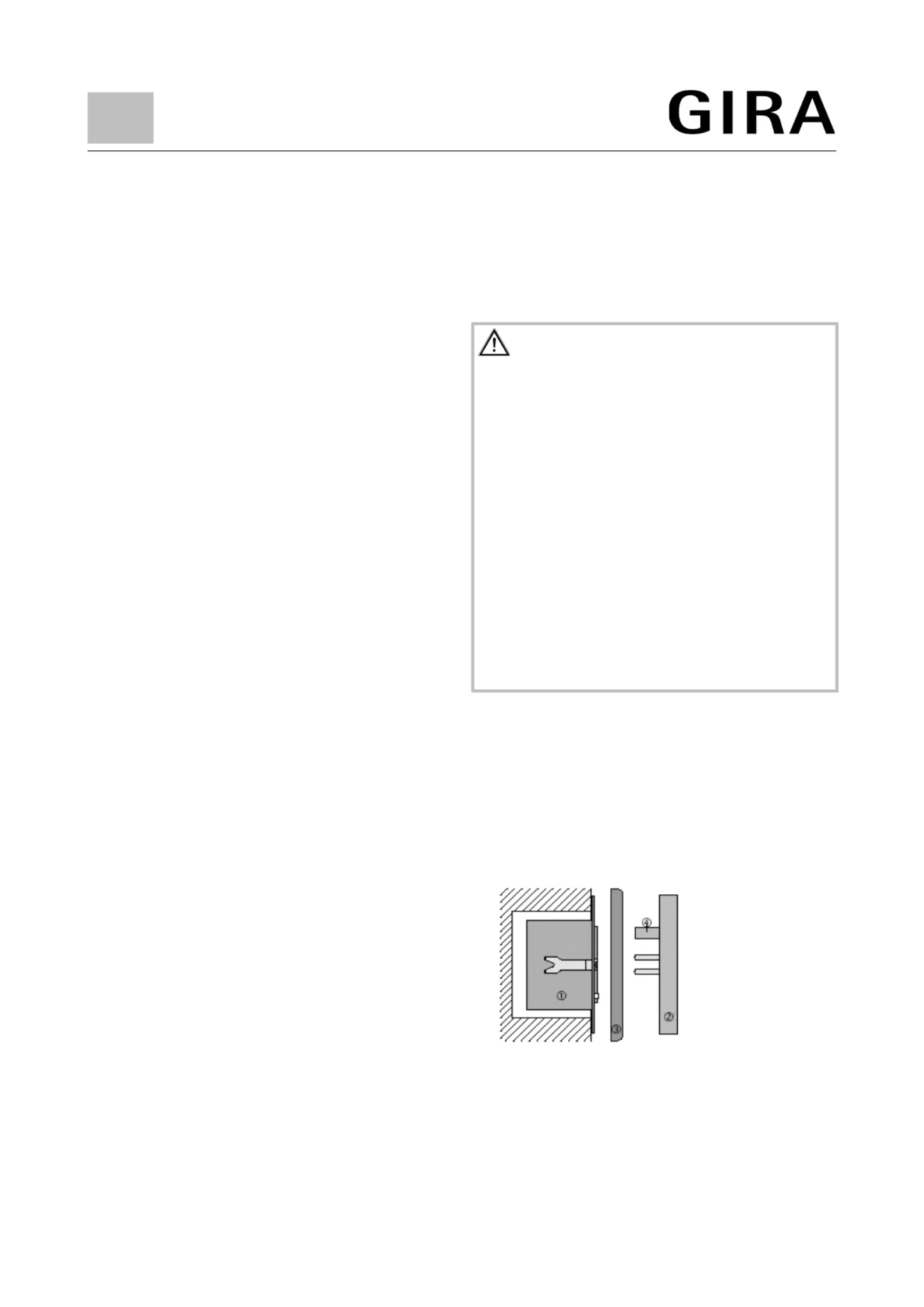
Installation Instructions
Install relay insert cin a box as per DIN 49073
(Figure A).
The connecting terminals of the insert must be down.
Do not use the relay insert when not in combination
with an attachment.
Plug attachment donto the insert together with frame
e.
Electrical contacting is established through plug f.
Plug on the cover prior to switching on the mains volt-
age.
Mains failures of more than 1 sec. will lead to switch-
ing off the relay insert.
A
System 2000 Relay-InsertOrder no.: 0853 00
Warning
Caution: The installation and assembly of electrical
equipment may only be performed by a skilled elec-
trician.
Not suitable for disconnecting.
To prevent electric shocks, always shut off the mains
supply (by cutting out the circuit-breaker) before
working on the device or before replacing the lamp.
For operation with conventional transformers, pro-
tect the primary side of each transformer by a fuse,
according to the manufacturer’s information. Do not
use any devices other than safety transformers as
per DIN VDE 0551.
Non-observance of the installation instructions may
cause fire or other hazards.
Produktspecifikationer
| Varumärke: | Gira |
| Kategori: | Rörelsedetektorer |
| Modell: | System 2000 |
| Certifiering: | CE |
| Antal kontakter: | 3 |
| Produktens färg: | Metallisk |
| Temperatur vid drift: | -20 - 45 ° C |
| AC-inspänning: | 230 V |
| Växelström Frekvens: | 50 - 60 hz |
| Ström: | 10 A |
Behöver du hjälp?
Om du behöver hjälp med Gira System 2000 ställ en fråga nedan och andra användare kommer att svara dig
Rörelsedetektorer Gira Manualer

3 Augusti 2024
30 Juli 2024
29 Juli 2024
26 Juli 2024
Rörelsedetektorer Manualer
Nyaste Rörelsedetektorer Manualer
9 Januari 2025
10 Oktober 2024
6 Oktober 2024
4 Oktober 2024
3 Oktober 2024
30 September 2024
27 September 2024
24 September 2024
22 September 2024
17 September 2024