Gossen Metrawatt METRALINE VT LED M611G Bruksanvisning
Gossen Metrawatt mätning METRALINE VT LED M611G
Läs gratis den bruksanvisning för Gossen Metrawatt METRALINE VT LED M611G (2 sidor) i kategorin mätning. Guiden har ansetts hjälpsam av 29 personer och har ett genomsnittsbetyg på 4.4 stjärnor baserat på 5 recensioner. Har du en fråga om Gossen Metrawatt METRALINE VT LED M611G eller vill du ställa frågor till andra användare av produkten? Ställ en fråga
Sida 1/2
Operating Instructions
3-447-271-15
1/9.24
METRALINE VT LED (M611G)
2-Pole Voltage Tester
according to DIN EN IEC 61243-3
© Gossen Metrawatt GmbH
Prepared in Germany • Subject to change, errors excepted • A pdf
version is available on the Internet
All trademarks, registered trademarks, logos, product names, and
company names are the property of their respective owners.
Gossen Metrawatt GmbH
Südwestpark 15
90449 Nürnberg
Germany
Phone: +49 911 8602-0
Fax: +49 911 8602-669
www.gossenmetrawatt.com
Content
1 Safety instructions
2 Application
3 Documentation
4 The device
5 Operation
6 Conducting measurements/tests
7 Exchange of batteries
8 Storage and Transport
9 Maintenance
10 Repair
11 Contact, support and service
1 Safety instructions
Read and follow these instructions carefully and complete-
ly in order to ensure safe and proper use.
The instructions must be made available to all persons
who use the device.
Keep for future reference.
General
•Thedevicemayonlybeusedbyqualiedelectriciansinthe
commercialeld.
• Observe and comply with all safety regulations which are appli-
cable for your work environment.
• Wear suitable and appropriate personal protective equipment
(PPE) whenever working with the device.
• The functioning of active medical devices (for example pace-
makers,debrillators)andpassivemedicaldevicesmaybe
affectedbyvoltages,currentsandelectromagneticelds
generated by the tester and the health of their users may be
impaired. Implement corresponding protective measures in
consultation with the manufacturer of the medical device and
your physician. If any potential risk cannot be ruled out, do not
use the device.
Accessories
•Useonlythespeciedaccessories(includedinthescopeof
delivery or listed as options) with the device.
Handling
•Thetestermaybeusedonlywithinthespeciedmeasurement
ranges and in low-voltage installations up to 1000 V
AC
/ 1500 V
DC
.
• Hold the tester and accessories by the designated grip areas
only, the display elements must not be covered.
• Before and after use, always conduct the self-test and check
that the tester is in perfect working order (e.g. on a known
voltage source).
• Use the device in undamaged condition only.
Inspect the device before use. Pay particular attention to
damage, interrupted insulation or kinked cables. Damaged
components must be replaced immediately.
• Use the accessories and all cables in undamaged condition only.
Inspect accessories and all cables before use. Pay particular
attention to damage, interrupted insulation or kinked cables.
•Ifthedeviceoritsaccessoriesdon’tfunctionawlessly,per-
manently remove the device/accessories from operation and
secure them against inadvertent use.
• If the device or accessories are damaged during use, for exam-
ple if they’re dropped, permanently remove the device/acces-
sories from operation and secure them against inadvertent use.
• If there are any signs of interior damage to the device or
accessories (e.g. loose parts in the housing), permanently re-
move the device/accessories from operation and secure them
against inadvertent use.
• The devices and accessories of Gossen Metrawatt GmbH are
designed such as to ensure optimum compatibility with the
Gossen Metrawatt GmbH products that are expressly provided
forthem.Unlessotherwiseexpresslyconrmedinwritingby
Gossen Metrawatt GmbH, they are not intended and suited for
use with other products.
• The device and the accessories may only be used for the tests/
measurements described in the documentation for the device.
Operating conditions
• Do not use the device and its accessories after long periods
of storage under unfavorable conditions (e.g. humidity, dust or
extreme temperature).
• Do not use the device and its accessories after extraordinary
stressing due to transport.
•Do not expose the device to direct sunlight.
• Only use the device and its accessories within the limits of the
speciedtechnicaldataandconditions(ambientconditions,IP
protection code, measuring category etc.).
• Do not use the device in potentially explosive atmospheres.
Danger of explosion!
•Donotusethedeviceinatmospheressubjecttorehazard.
Dangerofre
Regular batteries
• Without batteries the device only has a limited functionality:
If the batteries are empty or if there are no batteries insert-
ed into the device, only the LED for dangerous voltage
lights up if a voltage of 50 V
AC
/ 120 V
DC
is present.
Therefore, if possible, operate the device with batteries.
• Use batteries in undamaged condition only. Risk of explo-
sionandreinthecaseofdamagedbatteries!
Inspect the batteries before use. Pay particular attention to
leaky and damaged batteries.
• Only use the device with inserted and secured battery com-
partment lid. Otherwise, dangerous voltages may occur at the
battery contacts under certain circumstances.
Measurement cables and establishing contact
•Never touch conductive ends (for example of test probes).
• Ensure that the probes make good contact.
• Do not move or remove as far as possible plugs, test probes,
alligator clips or Kelvin probes until testing/measurement has
been completed.
Unwanted sparking may otherwise occur due to test current.
2 Application
Please read this important information!
2.1 Intended use / Use for intended purpose
The METRALINE VT LED is a universally applicable testing
deviceforvoltagetesting,single-polephasetesting,rotaryeld
testing, trip testing of RCDs, continuity testing and diode testing.
ThedevicefullsDINENIEC61243-3andbeenconstructed
and tested in accordance with the safety regulations for voltage
testers.
2.2 Use for other than intended purpose
Using the device for any purposes other than those described in
these device operating instructions is contrary to use for intended
purpose. Use for purposes other than those intended may result in
unforeseeable damage!
2.3 Liability and guarantee
The warranty provided by Gossen Metrawatt GmbH, and its liability,
are governed by the applicable contractual and mandatory statutory
provisions.
3 Documentation
Labelling in this document:
DANGER!
DANGER! Dangerous voltage. Danger of electrical shock.
Note! Important information.
4 The device
4.1 Scope of delivery
1 METRALINE VT LED
2 4 mm test tip adapters (round pins)
(in retainer at test tip cover))
2 Safety caps, screw-on for CAT IV 600 V / CAT III 1000 V /
GS-38, in retainer at test tip cover
1 Test tip cover (attached to the cable)
2 Batteries (1.5V, IEC AAA)
1 Operating instructions (this document)
Please check the scope of delivery for completeness and intactness.
4.2 Optional accessories
•Pouch (Z611T)
See datasheet for more information.
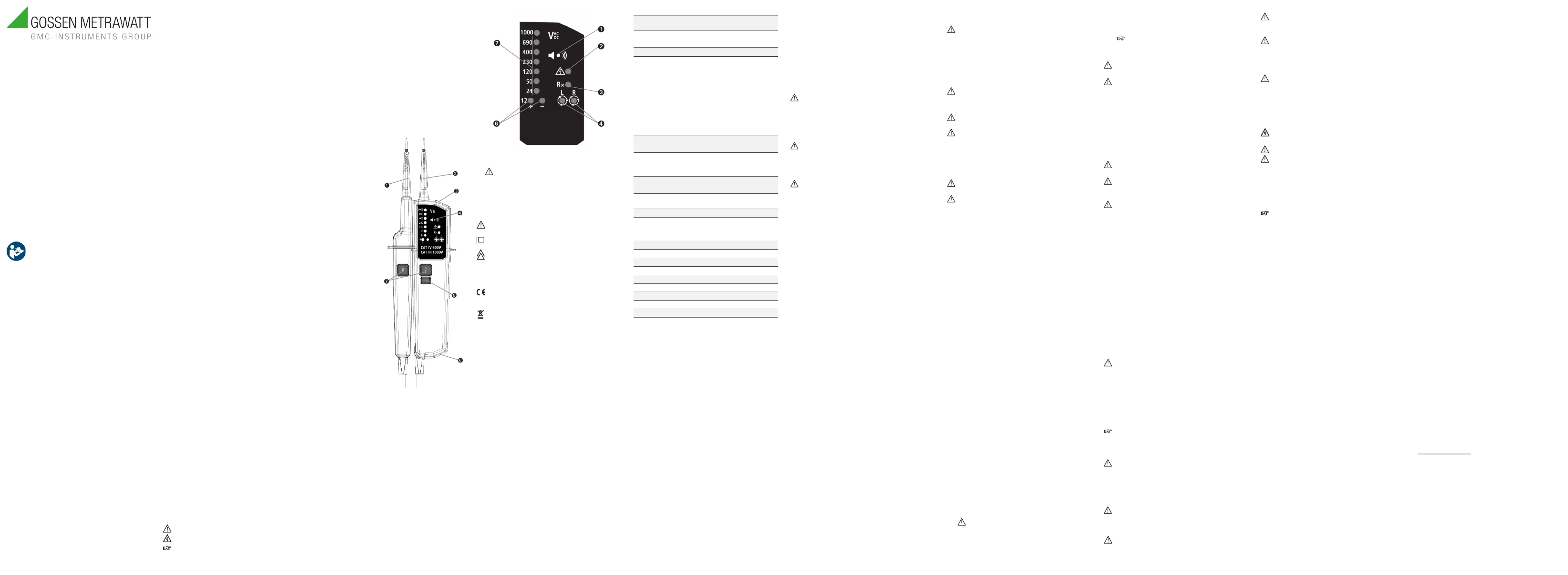
4.3 Device overview and control elements
1. Test tip L1 –
2. Test tip L2 +
3. Torch light
4. Buzzer
5. Function button:
device on and off /
turns on torch light
6. Battery compartment
7. RCD trip buttons /
load connection buttons
4.4 Indicators
1. Buzzer
2. Single pole test /
LED dangerous voltage warning
3. Continuity test LED
4. RotaryeldindicationLEDs
5. LEDs for indication of ±12 V and polarity
6. Voltage indication (steps)
4.5 Symbols on the device
Warning of a potential danger. Read and follow the operating
instructions.
Continuous double or reinforced insulation category II (DIN
EN IEC 61140).
Equipment for working under live voltage.
CAT II 1000 V Measurement category
CAT III 1000 V
CAT IV 600 V
EUconformitymarking,conrmscompliancewithapplicable
EU directives.
YoucanndtheCEdeclarationonourwebsite.
The device may not be disposed of with household trash. You
are required to comply with all applicable local regulations.
Further information regarding disposal can be found on our
website.
4.6 Included features
TheMETRALINEVTLCDischaracterizedbythefollowingfeatures:
• Measurement category: CAT IV 600 V, CAT III 1000 V,
CAT II 1000 V
• Voltage test from 0.5 V
AC
… 1000 V
AC
and 0.5 V
DC
…1500 V
DC
•Automatic polarity indication
•Single-pole phase test
•2-polerotaryeldindicationagainstearth
•Trip test of residual-current devices (RCDs)
•Continuity test/diode test
•Diode test with foward voltage drop display
•Integrated torch light for measuring point illumination
•Auto-power on and off
•Buzzer
•Vibration
4.7 Technical data
Measurement
category:
CAT III 1000 V / CAT IV 600 V
Measurement duty: :
30 s on (operation time)
240 s off (recovery time)
Peak current: I
s
< 3,5 mA (at 1000 V)
LED
Voltage range:
12 V
AC
/ 24 V
AC
/ 50 V
AC
/ 120 V
AC
/ 230
V
AC
/ 400 V
AC
/ 690 V
AC
/ 1000 V
AC
(16
2
/
3
Hz…950Hz)
12 V
DC(±)
/ 24 V
DC(±)
/ 50 V
DC(±)
/ 120 V
DC(±)
/
230 V
DC(±)
/ 400 V
DC(±)
/ 690 V
DC(±)
/ 1000 V
DC(±)
Tolerances: according to
DIN EN IEC 61243-3
Dangerous voltage warning:
> 50 V
AC
, > 120 V
DC
Response time:
LED < 0.5 s at 100 % of each nominal
voltage
Voltage range:
0.5 V
AC
… 1000 V
AC
(16
2
/
3
Hz…950Hz)
0.5 V
DC(±)
… 1500 V
DC(±)
Single-pole phase
test:
Range: 100 V
AC
… 1000 V
AC
(40Hz…70Hz)
Phase rotation test:
Range: 170 V … 1000 V phase-to-
phase,AC40Hz…70Hz
Continuity test:Detectionrange:0kΩ…500kΩ+50%
Temperature:
Operation: –15 °C… 50 °C
Storage: –20 °C … 60°C,
no condensation
Humidity: Max. 85% relative humidity
Altitude above NN: 2000 m
Pollution degree:2
Protection class: IP64
Power supply: 2 × battery (IEC AAA 1,5V)
Battery consumption:approx. 80 mA
Weight:approx. 275 g
Dimensions:approx. 280 mm × 75 mm × 35 mm
Cable length;approx. 113 cm
5 Operation
5.1 Switching on
The device automatically switches on if it detects continuity, an AC
or DC voltage above approx. 6 V, or a live phase on L2.
Alternatively, it can be switched on with the function button.
5.2 Switching off
The device is automatically powered off after 30 s if there is no
signal contacted to the probes.
The torch light switches off after approx. 30 s.
5.3 Self-test
Do not use the device during the self-test.
The self-tests starts if the device is off and both probes L1 – and L2
+ are shorted.
The self-test will start automatically when replacing batteries.
Expectedresult:AllLEDs,thebuzzer,andthevibrationswitchon
for 2 s.
If(someof)theLEDs,orthebuzzer,orthetorch
light do not switch on, the device is not safe for use.
Restart the self-test again. If the result is not the expected
result (see above), the device must be removed permanently
from operation and has to be secured against inadvertent use.
If the battery symbol is displayed continuously on the display, the
batteries are empty and must be replaced. See chapter „s
Exchange of batteries“.
5.4 Torch light
Pressing the function button will turn on the torch light and after
approx. 30 s it will turn itself off.
When torch light is on, pressing the function button about 6 s will
turn it off.
6 Conducting measurements/tests
6.1 General information
Before and after use, always conduct the self-test and check
that the tester is in perfect working order (e.g. on a known
voltage source).
Measurement category with screwed-on safety cap:
CAT IV 600 V, CAT III 1000 V
Measurement category without screwed-on safety cap: CAT II 1000
V
For tests/measurements of Schuko sockets, the 4 mm test tip adapt-
ers (round pins) are to be screwed onto the test tips.
Put the test tip cover on if you do not work with the device to
prevent injuries and damage to the test tips.
6.2 Voltage test with polarity indication
To determine the absence of voltage, 2 results must be
achieved: No voltage and no indication of polarity.
The voltage indication is battery independent. However,
without batteries the device only has a limited functionality:
If the batteries are empty or if there are no batteries inserted
into the device, only the LED for dangerous voltage lights
up if a voltage of 50 V
AC
/ 120 V
DC
is present.
Therefore, if possible, operate the device with batteries. See
chapter „s Exchange of batteries“.
The voltage indication (steps) via LED must not be used as
measurement. It is only an indication of voltage range.
Depending on the internal impedance (internal resistance)
of the voltage detector there will be a different capability of
indicating the presence or absence of operating voltage in
case of the presence of interference voltage.
•Low impedance voltage detectors:
A voltage detector of relatively low internal impedance,
comparedtothereferencevalueof100kΩ,willnot
indicate all interference voltages having an original
voltage value above the ELV level. When in contact
with the parts to be tested, the voltage detector may
discharge temporarily the interference voltage to a level
below the ELV, but it will be back to the original value
when the voltage detector is removed.
When the indication “voltage present” does not appear,
it is highly recommended installing earthing equipment
before work.
•High-impedance voltage detectors:
A voltage detector of relatively high internal impedance,
comparedtothereferencevalueof100kΩ,maynotper-
mit to clearly indicate the absence of operating voltage in
case of presence of interference voltage.
When the indication “voltage present” appears on a part
that is expected to be disconnected of the installation, it is
highlyrecommendedconrmingbyanothermeans(e.g.
use of an adequate voltage detector, visual check of the
disconnecting point of the electric circuit, etc.) that there is
no operating voltage on the part to be tested and to con-
clude that the voltage indicated by the voltage detector is
an interference voltage.
•Voltage detectors with load connection:
A voltage detector declaring two values of internal im-
pedance has passed a performance test of managing
interference voltages and is (within technical limits) able
to distinguish operating voltage from interference voltage
and has a means to directly or indirectly indicate which
type of voltage is present.
•Connect both test tips to the object under test.
•Optional: By pressing both the load connection buttons simulta-
neously, an internal load will be connected, i.e. the impedance
is lowered, so that inductively/capacitively induced interference
voltagesaresuppressedanddonotinuencetheresult.
•Result:
If a life endangering threshold voltage 50 V
AC
or approx.
120 V
DC
is exceeded, the LED for dangerous voltage lights
up and the device warns acoustically and vibrates.
•The voltage is indicated by the LEDs and on the display.
• The polarity is indicated in following manner:
12 V + – LEDs light up = alternating current
12 V + LED lights up = positive direct current
12 V – LED lights up, display shows „–“ = negative direct
current
• When the L2 test tip is connected with a positive (negative)
potential, the LED 12 + (–) lights up.
During the voltage test, the L or R LED may light up. This
is due to technical reasons and does not signify anything.
6.3 Single-pole phase test
The single-pole phase test must not be used to determine the
absence of voltage.
Proper function of this test is not be fully achieved if the
grounding conditions aren’t good enough. Insulating proper-
ties can adversely affect the test.
•Connect the L2 test tip to the object under test.
• Result:
ThesinglepoletestLEDlightsupandthebuzzersoundsifa
voltageof≥100V
AC
exists in the object under test.
6.4 Rotary eld test
Measurement principle: The device detects the phase rising order
regarding the user as earth.
Correct results can be obtained only on properly grounded
three-phase 4-wire systems.
Proper function of this test is not be fully achieved if the
grounding conditions aren’t good enough. Insulating proper-
ties can adversely affect the test.
Conduct a counter test, to verify the result. To do so, switch
the test tips around; the expected result is swapped display of
the result.
•Connect both test tips to the object under the test.
•Results:
• Phase-to-phase voltage is indicated via the voltage indica-
tion LEDs.
•TheRLEDlightsupforrightrotaryeld.
•TheLLEDlightsupforleftrotaryeld.
6.5 RCD trip test
For voltage tests in systems with RCDs (residual-current device,
also ground fault circuit interrupter – GFCI), an RCD can be tripped
with a 10 m A or 30 mA nominal leakage current in a single phase
AC 230 V power system.
•Connect the two test tips L and PE.
•Push both RCD trip buttons simultaneously.
• Expected result: The RCD trips.
If the RCD doesn’t trip, the system must be checked.
6.6 Continuity test (Rx)/Diode test
Conrmthattestcircuit/objectisvoltagefreewitha2-pole
voltage tester. See voltage tests.
•Turn the device on. See chapter 5.1 „Switching on“.
• Connect both test tips to the test object.
•Result:
•Forcontinuity(uptoapprox.500kΩ)thecontinuitytestLED
andthedeviceisbuzzing.
• If no continuity is detected, the device off after approx. 30 s.
Exchange of batteries
Empty batteries are indicated by an symbol on the display.
If the test tips are shortened and the continuity test LED does not
light up, the batteries must be replaced.
Onlyinsertbatteriesaccordingtothespecicationfoundin
the technical data.
• Unscrew the battery cover and open it.
• Remove the empty batteries and insert new batteries according
to the polarity indicated on the device.
• Close the battery door and screw it closed.
Do not throw used batteries into the household trash. Observe
the local regulations for disposal.
7 Storage and transport
Improper storage
Damage to the product and measuring error
duetoenvironmentalinuences.
Store the device in a protected location and only within the
limits of permissible ambient conditions.
Remove the batteries when the device will not be in use for a
longerperiodinordertopreventpossiblehazardordamage
due to potentially leaking batteries.
Improper transport
Damage to the product and measuring error.
Transport the device only within the limits of per-
missible ambient conditions (temperature, humidity.
Onlytransportthedevicewithsufcientprotection.
Remove batteries when the device will not be in use for a long
period.
8 Maintenance
The device does not need any special maintenance if it is used
according to these operating instructions.
Cleaning
Turn off the device and remove it from all test points before
cleaning.
Never use abrasives or solvents.
Wait until the device is fully dry after cleaning, before you use
it again.
Use a lightly damp cloth with neutral detergent for cleaning the
device.
9 Repair
If your device requires repair, please contact our service department.
Loss of warranty and guarantee claims
Unauthorizedmodicationofthedeviceisprohibited.This
also includes opening the device. If it can be ascertained that
thedevicehasbeenopenedbyunauthorizedpersonnel,no
guarantee claims can be honored by the manufacturer with re-
gard to personal safety, measuring accuracy, compliance with
applicable safety measures or any consequential damages.
Thedevicemayonlyberepairedoropenedbyauthorized,qualied
personnel who are familiar with the associated dangers. Original
replacementpartsmayonlybeinstalledbyauthorized,qualied
personnel.
10 Contact, support and service
Gossen Metrawatt GmbH can be reached directly and simply – we
have a single number for everything! Whether you require support
or training, or have an individual inquiry, we can answer all of your
questions here:
+49-911-8602-0
Monday to Thursday: 8 a.m. to 4 p.m.
Friday: 8 a.m. to 2 p.m.
Or contact us by e-mail at: [email protected]
Do you prefer support by e-mail?
Measuring and Test Technology:
Industrial Measuring Technology:
Please contact GMC-I Service GmbH for repairs, replacement parts
and calibration1:
+49-911-817718-0
Beuthener Str. 41, 90471 Nürnberg, Germany
https://www.gmci-service.com/en/
1 DAkkS calibration laboratory per DIN EN ISO/IEC 17025
accredited by the Deutsche Akkreditierungsstelle GmbH
under reference number D-K-15080-01-01.
Produktspecifikationer
| Varumärke: | Gossen Metrawatt |
| Kategori: | mätning |
| Modell: | METRALINE VT LED M611G |
Behöver du hjälp?
Om du behöver hjälp med Gossen Metrawatt METRALINE VT LED M611G ställ en fråga nedan och andra användare kommer att svara dig
mätning Gossen Metrawatt Manualer

6 Oktober 2025
6 Oktober 2025
3 Augusti 2025
3 Augusti 2025
3 Augusti 2025
3 Augusti 2025
3 Augusti 2025
3 Augusti 2025
3 Augusti 2025
3 Augusti 2025
mätning Manualer
Nyaste mätning Manualer
3 April 2026
3 April 2026
2 April 2026
2 April 2026
31 Mars 2026
30 Mars 2026
30 Mars 2026
30 Mars 2026
28 Mars 2026
24 Mars 2026