Gossen Metrawatt SINEAX CAM Bruksanvisning
Gossen Metrawatt mätning SINEAX CAM
Läs gratis den bruksanvisning för Gossen Metrawatt SINEAX CAM (12 sidor) i kategorin mätning. Guiden har ansetts hjälpsam av 56 personer och har ett genomsnittsbetyg på 4.5 stjärnor baserat på 3 recensioner. Har du en fråga om Gossen Metrawatt SINEAX CAM eller vill du ställa frågor till andra användare av produkten? Ställ en fråga
Sida 1/12
Camille Bauer Metrawatt Ltd.
Aargauerstrasse 7
CH-5610 Wohlen/Switzerland
Phone +41 56 618 21 11
Fax +41 56 618 21 21
www.camillebauer.com
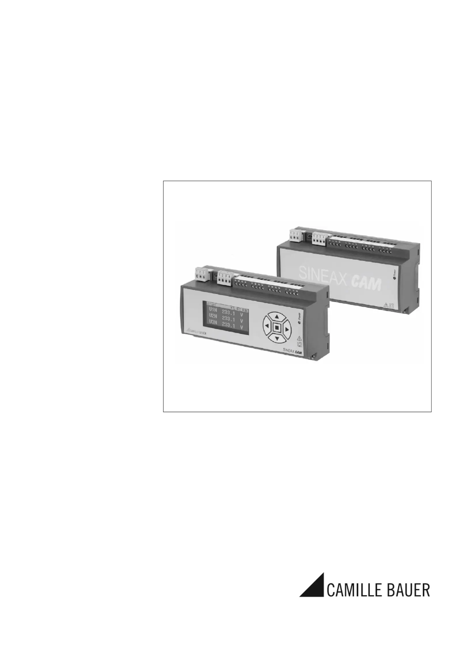
Operating Instructions
Universal measuring unit for heavy current variables
SINEAX CAM
CAM Be 156 481-14 08.14
Produktspecifikationer
| Varumärke: | Gossen Metrawatt |
| Kategori: | mätning |
| Modell: | SINEAX CAM |
Behöver du hjälp?
Om du behöver hjälp med Gossen Metrawatt SINEAX CAM ställ en fråga nedan och andra användare kommer att svara dig
mätning Gossen Metrawatt Manualer

6 Oktober 2025
6 Oktober 2025
3 Augusti 2025
3 Augusti 2025
3 Augusti 2025
3 Augusti 2025
3 Augusti 2025
3 Augusti 2025
3 Augusti 2025
3 Augusti 2025
mätning Manualer
Nyaste mätning Manualer
3 April 2026
3 April 2026
2 April 2026
2 April 2026
31 Mars 2026
30 Mars 2026
30 Mars 2026
30 Mars 2026
28 Mars 2026
24 Mars 2026