Humminbird 678c Bruksanvisning
Humminbird fishfinder 678c
Läs gratis den bruksanvisning för Humminbird 678c (104 sidor) i kategorin fishfinder. Guiden har ansetts hjälpsam av 49 personer och har ett genomsnittsbetyg på 4.1 stjärnor baserat på 7 recensioner. Har du en fråga om Humminbird 678c eller vill du ställa frågor till andra användare av produkten? Ställ en fråga
Sida 1/104
532173-1EN_A
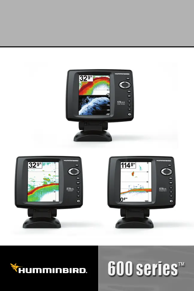
678cHD,678cHDDI,and678cHDXD
OperationsManual
678cHD,678cHDDI,and678cHDXD
OperationsManual
Produktspecifikationer
| Varumärke: | Humminbird |
| Kategori: | fishfinder |
| Modell: | 678c |
| Skärm diagonal: | 5 " |
| Upplösning: | 480 x 640 pixlar |
| Bakgrundsbelysning: | Ja |
| Maximalt djup: | 182.88 m |
| Toppeffekt: | 4000 W |
| Uteffekt (RMS): | 500 W |
| Produktstorlek (BxDxH): | 108.12 x 114.3 x 190.5 mm |
| Displaytyp: | TFT LCD |
| Vatten temperaturgivare: | Ja |
Behöver du hjälp?
Om du behöver hjälp med Humminbird 678c ställ en fråga nedan och andra användare kommer att svara dig
fishfinder Humminbird Manualer

8 Oktober 2024
11 September 2024
11 September 2024
11 September 2024
11 September 2024
4 September 2024
27 Augusti 2024
24 Augusti 2024
24 Augusti 2024
21 Augusti 2024
fishfinder Manualer
Nyaste fishfinder Manualer
8 Mars 2025
7 Januari 2025
1 Januari 2025
30 December 2025
26 September 2024
21 September 2024
19 September 2024
18 September 2024
15 September 2024
13 September 2024