Intermatic T106M Bruksanvisning
Intermatic brytare T106M
Läs gratis den bruksanvisning för Intermatic T106M (4 sidor) i kategorin brytare. Guiden har ansetts hjälpsam av 17 personer och har ett genomsnittsbetyg på 4.9 stjärnor baserat på 8 recensioner. Har du en fråga om Intermatic T106M eller vill du ställa frågor till andra användare av produkten? Ställ en fråga
Sida 1/4
T100 SERIES MECHANISM INSTRUCTION SHEET
24 Hour Dial Time Switch Mechanisms
WARNING
Risk of Fire or Electric Shock
• Disconnect power at the circuit breaker(s) or disconnect switch(es) before installing or servicing.
• Installation and/or wiring must be in accordance with national and local electrical code requirements.
• Use wires rated at least 90°C - COPPER conductors ONLY.
• Replace plastic insulator covering terminals before powering ON.
• KEEP DOOR CLOSED AT ALL TIMES when not servicing.
NOTICE
NOTICE
NOTICE
NOTICENOTICE
• Rotate timer dial clockwise only.
• Do not move the clock hands on the timer. Moving the clock hands can damage the timer.
40 A RESISTIVE, INDUCTIVE, TUNGSTEN
OR 1000 VA PILOT DUTY 120/208/240 VAC;
2 HP (24 FLA) - 120 VAC; 5 HP (28 FLA) - 240 VAC
16 A ELECTRONIC BALLAST, 277 VAC
Load Ratings:
T101M/T103M/T106M:
40 A RESISTIVE EACH POLE, 120-480 VAC
40 A INDUCTIVE, TUNGSTEN OR 1000 VA
PILOT DUTY EACH POLE 120V-277 VAC;
2 HP (24 FLA) - 120 VAC; 5 HP (28 FLA) - 240 VAC
16 A ELECTRONIC BALLAST, 277 VAC
T104M:
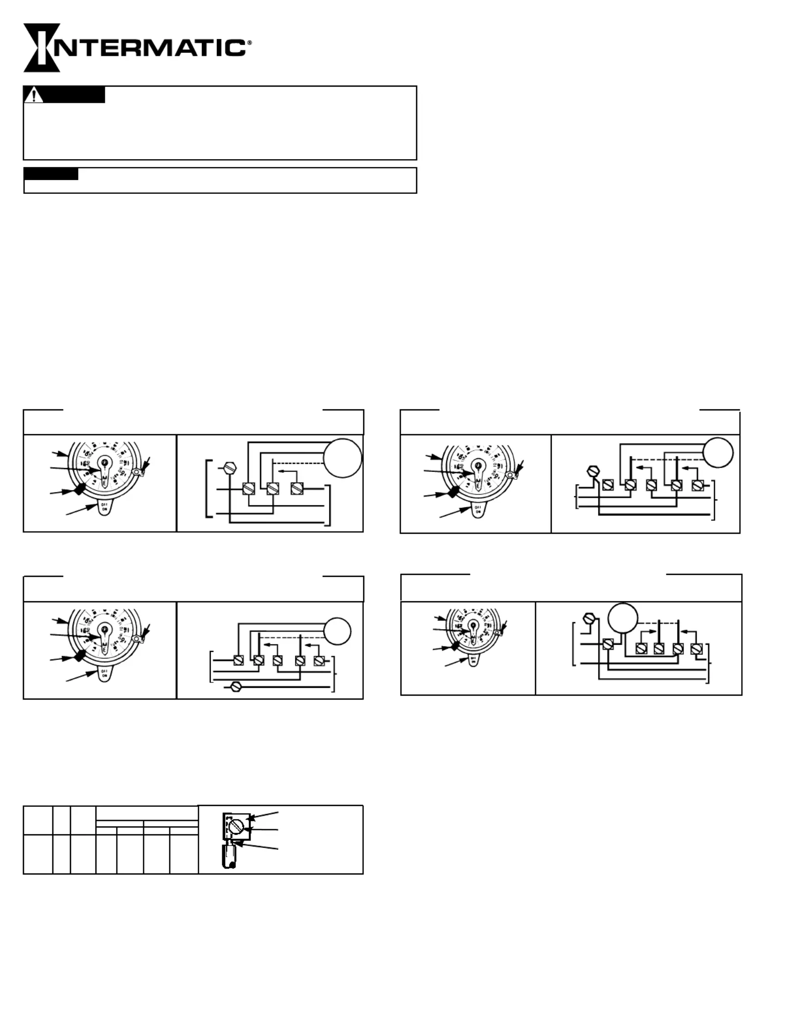
Wiring Diagrams:
CLOCK MOTOR: 120 VAC, 60 HZ.
CLOCK MOTOR VOLTAGE AND CYCLE MUST BE AS SPECIFIED. TO
ORDER REPLACEMENT, INDICATE PART NO. (WG--) ON MOTOR COVER.
TIME
POINTER
TIME
DIAL
OFF
TRIPPER
MANUAL
LEVER
ON
TRIPPER
LINE
NEUT.
CLOCK
MOTOR
GROUND
A
1
2
GRD.
120V
SUPPLY
TO
LOAD
WIRING
DIAGRAM
T101M: SINGLE POLE SINGLE THROW (SPST)
TIME
POINTER
TIME
DIAL
OFF
TRIPPER
MANUAL
LEVER
ON
TRIPPER
CLOCK MOTOR: 208-277 VAC, 60 HZ.
CLOCK MOTOR VOLTAGE AND CYCLE MUST BE AS SPECIFIED. TO
ORDER REPLACEMENT, INDICATE PART NO. (WG--) ON MOTOR COVER.
CLOCK
MOTOR
GROUND
A
1
2
3
4
GR
240V
SUPPLY
TO
LOAD(S)
LINE 1
LINE 2
277/480 VOLT CONNECT MOTOR LEADS TO TERMINALS
“A” AND 1 AND SUPPLY NEUTRAL TO TERMINAL “A”.
WIRING
DIAGRAM
240 V 2 WIRE
AND GROUND
CLOCK MOTOR: 120 VAC, 60 HZ.
CLOCK MOTOR VOLTAGE AND CYCLE MUST BE AS SPECIFIED. TO
ORDER REPLACEMENT, INDICATE PART NO. (WG--) ON MOTOR COVER.
TIME
POINTER
TIME
DIAL
OFF
TRIPPER
MANUAL
LEVER
ON
TRIPPER
TYPICAL
WIRING
DIAGRAM
CLOCK
MOTOR
120/240
VOLT
3 WIRE
SUPPLY
TO
LOADS
GROUND
LINE 2
LINE 1
A
4
2
GR.
3
1
NEUT.
T104M: DOUBLE POLE SINGLE THROW (DPST)
T103M: DOUBLE POLE SINGLE THROW (DPST)
T106M: ONE NORMALLY OPEN, ONE NORMALLY CLOSED CONTACTS - (CAN BE WIRED AS SPDT)
CLOCK MOTOR VOLTAGE AND CYCLE MUST BE AS SPECIFIED. TO
ORDER REPLACEMENT, INDICATE PART NO. (WG--) ON MOTOR COVER.
CLOCK
MOTOR
WIRING DIAGRAM
FROM
208V
240V
OR
277V
SUPPLY
TO
LOAD
GROUND
LINE
GRD
A
4321
CLOCK
DIAL
TIME
POINTER
OFF
TRIPPER
MANUAL
LEVER
ON
TRIPPER
TYPICAL WIRING SINGLE POLE NORMALLY OPEN
SEE WIRING INSTRUCTIONS BELOW FOR OTHER TYPES
FIGURE 1
N
PRESSURE PLATE
TERMINAL SCREW
MAKE SURE WIRE
INSULATION CLEARS
PRESSURE PLATE
MINIMUM
COPPER
WIRE SIZE
(AWG)
MAX.
LOAD
(AMP)
MIN.
INSUL-
ATION
TEMP(°C)
75°C INSULATION MAX. MOTOR
LOAD (HP)
SINGLE PHASE
3 PHASE
120 V.240 V.208 V.
240 V.
14
12
10
8
15
20
30
40
90
90
90
90
1/2
1
2
-
2
2 1/2
3
5
N/A
N/A
Wiring Instructions: Remove 1/2 inch of insulation from wire ends. Tighten terminal screws firmly (2-18 in-lbs).
Use solid or stranded COPPER conductors only. May use two wires of the same size and type.
Programming Instructions:
1. TO SET “ON” AND “OFF” TIMES: Hold trippers against edge of CLOCK-DIAL, pointing to time (AM or PM) when ONand OFF
operations are desired, tighten tripper screws firmly. For additional tripper pairs on order 156T1978A.CLOCK-DIAL
2. TO SET TIME-OF-DAY:Pull CLOCK-DIALoutward. Turn in either direction and align the exact time-of-day on the CLOCK-DIAL
(the time now, when switch is being put into operation) to the pointer. DO NOT MOVE POINTER.
Operating Instructions:
•
TO OPERATE SWITCH MANUALLY: MANUAL LEVERMove
CLOCK-DIAL below left or right as indicated by arrows. This will not
effect next operation.
• IN CASE OF POWER FAILURE,reset CLOCK-DIALto proper time-of-day. See programming instructions.
CLOCK MOTOR: 208-277 VAC, 60 HZ.
WIRING INSTRUCTIONS: SINGLE POLE To wire switch follow diagram above. To wire as
NORMALLY CLOSED,move clock motor lead from terminal 3 to 1, and connect LINEto 1,
LOADto 2. To wire as , install jumper (the same gauge SINGLE POLE DOUBLE THROW
as line wire) between 2 and 3 and connect to 2, to 1 and 4. LINELOADSNOTE: Line 2 if
present is uninterrupted.
Produktspecifikationer
| Varumärke: | Intermatic |
| Kategori: | brytare |
| Modell: | T106M |
Behöver du hjälp?
Om du behöver hjälp med Intermatic T106M ställ en fråga nedan och andra användare kommer att svara dig
brytare Intermatic Manualer

4 Augusti 2025
4 Augusti 2025
3 Augusti 2025
3 Augusti 2025
3 Augusti 2025
3 Augusti 2025
brytare Manualer
Nyaste brytare Manualer
27 Mars 2026
26 Mars 2026
26 Mars 2026
24 Mars 2026
24 Mars 2026
23 Mars 2026
22 Mars 2026
22 Mars 2026
22 Mars 2026
21 Mars 2026