Joy-it RD6006 Bruksanvisning
Joy-it Inte kategoriserad RD6006
Läs gratis den bruksanvisning för Joy-it RD6006 (10 sidor) i kategorin Inte kategoriserad. Guiden har ansetts hjälpsam av 37 personer och har ett genomsnittsbetyg på 4.1 stjärnor baserat på 5 recensioner. Har du en fråga om Joy-it RD6006 eller vill du ställa frågor till andra användare av produkten? Ställ en fråga
Sida 1/10
LARGE CASE FOR RD
LARGE CASE FOR RD
LARGE CASE FOR RD
LARGE CASE FOR RDLARGE CASE FOR RD6006
6006
6006
60066006
JT--RD6006Case02
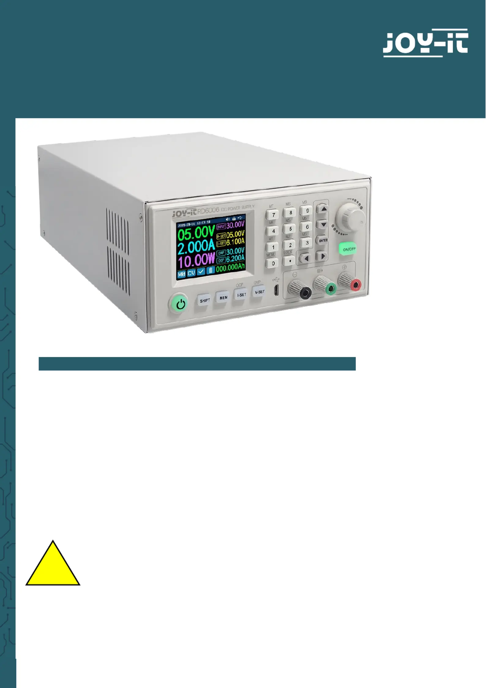
1. GENERAL INFORMATION
1. GENERAL INFORMATION
1. GENERAL INFORMATION
1. GENERAL INFORMATION1. GENERAL INFORMATION
Dear customer,
Thank you for purchasing our product. In the following, we will show you
which things should be noted during the use.
Should you encounter any unexpected problems, do not hesitate to
contact us.
This
This
This
This This case
case
case
case case is
is
is
is is available
available
available
available available in
in
in
in in two
two
two
twotwo
versions,
versions,
versions,
versions, versions, version
version
version
version version A
A
A
A A and
and
and
and and B.
B.
B.
B. B. These
These
These
These These vers
vers
vers
versversions
ions
ions
ions ions
dier
dier
dier
dier dier by
by
by
by by a
a
a
a a lead
lead
lead
leadleadout
out
out
out out o
o
o
oof
f
f
f f the
the
the
the the temperature
temperature
temperature
temperature temperature sensor,
sensor,
sensor,
sensor, sensor, whic
whic
whic
whicwhich
h
h
h h only
only
only
only only version
version
version
versionversion
B
B
B
B B
-
-
-
--
features.
features.
features.
features.features.
This case is made for an additional power supply which allows
you to connect this lab power supply directly to alternating
current.
Fo
Fo
Fo
FoFor your own safe
r your own safe
r your own safe
r your own safer your own safety
ty
ty
tyty, this p
, this p
, this p
, this p, this product ma
roduct ma
roduct ma
roduct maroduct may only be
y only be
y only be
y only be y only be
ins
ins
ins
insinstalle
talle
talle
talletalled by a qualified
d by a qualified
d by a qualified
d by a qualified d by a qualified electrician! Wo
electrician! Wo
electrician! Wo
electrician! Woelectrician! Working on
rking on
rking on
rking on rking on
electric devic
electric devic
electric devic
electric devicelectric devices / syst
es / syst
es / syst
es / systes / systems implies the haz
ems implies the haz
ems implies the haz
ems implies the hazems implies the hazard of
ard of
ard of
ard of ard of
electric shocks whic
electric shocks whic
electric shocks whic
electric shocks whicelectric shocks which
h
h
hh may cause serio
may cause serio
may cause serio
may cause serio may cause seriou
u
u
uus injuries or
s injuries or
s injuries or
s injuries or s injuries or
even de
even de
even de
even deeven death!
ath!
ath!
ath!ath!
!
Produktspecifikationer
| Varumärke: | Joy-it |
| Kategori: | Inte kategoriserad |
| Modell: | RD6006 |
Behöver du hjälp?
Om du behöver hjälp med Joy-it RD6006 ställ en fråga nedan och andra användare kommer att svara dig
Inte kategoriserad Joy-it Manualer

8 April 2025
8 April 2025
31 Januari 2025
29 Januari 2025
29 Januari 2025
15 Januari 2025
2 Januari 2025
28 December 2024
5 December 2024
5 December 2024
Inte kategoriserad Manualer
Nyaste Inte kategoriserad Manualer
9 April 2025
9 April 2025
9 April 2025
9 April 2025
9 April 2025
9 April 2025
9 April 2025
9 April 2025
9 April 2025
9 April 2025