Magic Chef MCSCTG12S Bruksanvisning
Magic Chef Ugn MCSCTG12S
Läs gratis den bruksanvisning för Magic Chef MCSCTG12S (44 sidor) i kategorin Ugn. Guiden har ansetts hjälpsam av 34 personer och har ett genomsnittsbetyg på 4.8 stjärnor baserat på 4 recensioner. Har du en fråga om Magic Chef MCSCTG12S eller vill du ställa frågor till andra användare av produkten? Ställ en fråga
Sida 1/44
1
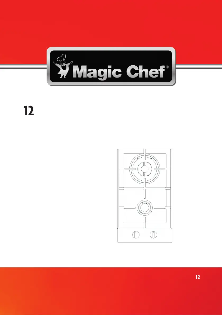
Model MCSCTGS
PLEASE READ THIS MANUAL CAREFULLY BEFORE USING YOUR
GAS COOKTOP AND KEEP IT FOR FUTURE REFERENCE.
-Inch Gas Cooktop
User’s Manual
Produktspecifikationer
| Varumärke: | Magic Chef |
| Kategori: | Ugn |
| Modell: | MCSCTG12S |
Behöver du hjälp?
Om du behöver hjälp med Magic Chef MCSCTG12S ställ en fråga nedan och andra användare kommer att svara dig
Ugn Magic Chef Manualer

10 December 2024
8 December 2024
9 September 2024
9 September 2024
8 September 2024
8 September 2024
8 September 2024
8 September 2024
8 September 2024
8 September 2024
Ugn Manualer
Nyaste Ugn Manualer
3 April 2026
2 April 2026
2 April 2026
2 April 2026
2 April 2026
2 April 2026
2 April 2026
2 April 2026
1 April 2026
1 April 2026