MB Quart MBQ-CAM-1 Bruksanvisning
MB Quart Inte kategoriserad MBQ-CAM-1
Läs gratis den bruksanvisning för MB Quart MBQ-CAM-1 (8 sidor) i kategorin Inte kategoriserad. Guiden har ansetts hjälpsam av 38 personer och har ett genomsnittsbetyg på 4.2 stjärnor baserat på 3 recensioner. Har du en fråga om MB Quart MBQ-CAM-1 eller vill du ställa frågor till andra användare av produkten? Ställ en fråga
Sida 1/8
CAUTION
Always consider consulting a professional installer before installing
any components. Be careful and take your time. Do not let wires
make contact with metal edges or hot engine components.
Congratulations on your choice of a MB Quart Auxiliary
Camera. This “Quick Start” Installation guide is meant to
help you complete a basic installation. Visit our website at
MBQuart.com for more detailed information.
Disconnect the negative battery terminal from the negative battery post
before installing.
MOUNTING LOCATION
Locate your desired switch and camera location. Mount the switch in
an open carling knockout. If you do not have an open carling knockout,
the unit itself requires a 0.83 inch (21mm) wide by 1.4 inch (37mm)
high opening with at least 2.5 inches of clearance behind the mounting
surface.
WIRE ROUTING
•Route wiring labeled P2,P3,P7 to the switch location.
•Route purple reverse wire and yellow RCA video cables to the
source unit/display.
•Route white 4 pin JST connector to the camera
mounting location.
•Route 12v, ACC, and GND wires to the vehicle battery or buss bar.
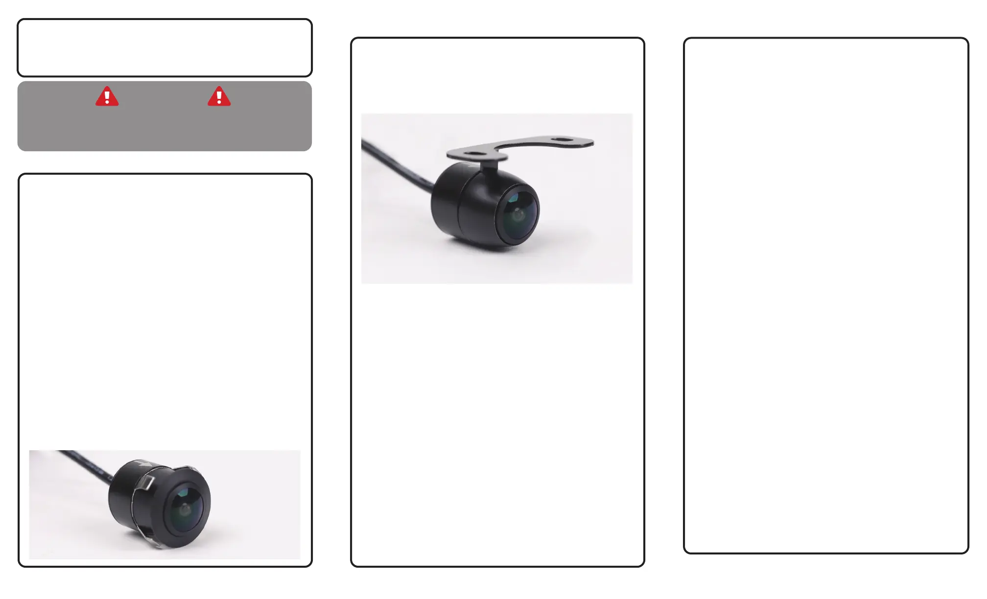
CAMERA FLUSH MOUNTING
The camera comes with the ush mount already attached
(shown below). If your install location doesn’t allow for ush mounting,
please see surface mounting instructions on page 2.
To ush mount the camera, use the supplied 18.5mm hole saw to drill
the hole, making sure there is adequate room behind the panel.
Camera/Switch Installation
CAMERA SURFACE/BRACKET MOUNTING
To surface mount the camera, using the supplied bracket, unscrew
the ush mount trim ring that comes on the camera. Next, screw
on the surface mount bracket. Secure the bracket to the mounting
location you have chosen.
Note - may need to attach bracket to vehicle panel prior to attaching to camera.
WIRING CONNECTIONS
Connect the white 4pin JST from the camera to the camera harness.
At this time you will connect the yellow RCA to the camera input of
your source unit or GMR7V1. Connect your camera’s reverse wire to
the camera trigger input on the radio. (See wiring diagram on page 4)
After all this is done, you can now connect the +12v, ACC, and GND
wires to the buss bar or battery and reconnect the negative battery
terminal to the negative battery post.
Camera/Switch Installation
Camera/Switch Installation
REVERSE CAMERA ONLY
If using as a reverse camera only - cut the loop (green wire) located
on the camera wiring. Then connect the reverse wire to the reverse
trigger wire of your source unit to activate as a reverse camera.
Features
IPX Rating
Horizontal Angle
Vertical Angle
Image Sensor
Optical Format
Signal Noise Ratio
Input Voltage
Mirror or Real Image
Parking Line
LED
EMC
IPX67/IP69K
150 °
170 °
1/3 ″ CMOS
NTSC
>48dB (AOC On)
12V DC
Both (Cut Loop)
NONE
NONE
RE-10
3 of 4
Produktspecifikationer
| Varumärke: | MB Quart |
| Kategori: | Inte kategoriserad |
| Modell: | MBQ-CAM-1 |
Behöver du hjälp?
Om du behöver hjälp med MB Quart MBQ-CAM-1 ställ en fråga nedan och andra användare kommer att svara dig
Inte kategoriserad MB Quart Manualer

16 September 2024
4 September 2024
24 Augusti 2024
23 Augusti 2024
13 Augusti 2024
9 Augusti 2024
8 Augusti 2024
8 Augusti 2024
6 Augusti 2024
5 Augusti 2024
Inte kategoriserad Manualer
Nyaste Inte kategoriserad Manualer
9 April 2025
9 April 2025
9 April 2025
9 April 2025
9 April 2025
9 April 2025
9 April 2025
9 April 2025
9 April 2025
9 April 2025