Megger 210170 Bruksanvisning
Läs gratis den bruksanvisning för Megger 210170 (6 sidor) i kategorin mätning. Guiden har ansetts hjälpsam av 45 personer och har ett genomsnittsbetyg på 5.0 stjärnor baserat på 7 recensioner. Har du en fråga om Megger 210170 eller vill du ställa frågor till andra användare av produkten? Ställ en fråga
Sida 1/6
M210170
Insulation &
Low Resistance Tester
User Guide
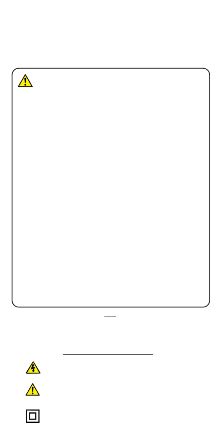
SAFETYWARNINGS
✱Safety Warningsread and understoodand mustbe Precautions
before the instrument is used. They must be during use.observed
✱The circuit under test mustbe switched o, de - energized and
isolated
before Insulation or Continuity tests are made.
✱Circuit connections be touched during a test.must not
✱The test button be pressed while connecting the test must not
leads or while changing ranges.
✱The ‘Testnot’button must be pressed when making a voltage test.
✱The Default VoltmeterAutomatic discharge, andare additional
safety features and
should notbe regarded as a substitute for
normal safe working practice.
✱The 210170is protected for connection to Power distribution
systems up to 300 V
LineGroundLineLine- , and 500 V - for
Installation Category III.*
✱It is recommended that fused test leads are used when measuring
voltage on high energy systems.
✱After insulation tests, capacitive circuits must be allowed to
discharge
beforedisconnecting the test leads.
✱Test leads, prods and alligator clips in good order; clean, must be
and with no broken or cracked insulation.
✱Replacement fuses of the correct size, type and rating.must be
Symbols used on the instrument
Caution: risk of electric shock
Caution: refer to accompanying notes
Equipment protected throughout by Double
Insulation (Class
II)
NOTE
THEINSTRUMENTMUSTONLYBEUSEDBYSUITABLYTRAINEDANDCOMPETENT
PERSONS.
Produktspecifikationer
| Varumärke: | Megger |
| Kategori: | mätning |
| Modell: | 210170 |
Behöver du hjälp?
Om du behöver hjälp med Megger 210170 ställ en fråga nedan och andra användare kommer att svara dig
mätning Megger Manualer

9 Augusti 2025
3 Augusti 2025
3 Augusti 2025
2 Augusti 2025
2 Augusti 2025
2 Augusti 2025
2 Augusti 2025
2 Augusti 2025
2 Augusti 2025
2 Augusti 2025
mätning Manualer
Nyaste mätning Manualer
3 April 2026
3 April 2026
2 April 2026
2 April 2026
31 Mars 2026
30 Mars 2026
30 Mars 2026
30 Mars 2026
28 Mars 2026
24 Mars 2026