Monacor CU-4BOOST Bruksanvisning
Monacor Wifi-repeater CU-4BOOST
Läs gratis den bruksanvisning för Monacor CU-4BOOST (4 sidor) i kategorin Wifi-repeater. Guiden har ansetts hjälpsam av 28 personer och har ett genomsnittsbetyg på 4.7 stjärnor baserat på 3 recensioner. Har du en fråga om Monacor CU-4BOOST eller vill du ställa frågor till andra användare av produkten? Ställ en fråga
Sida 1/4
ELECTRONICS FOR SPECIALISTS ELECTRONICS FOR SPECIALISTS ELECTRONICS FOR SPECIALISTS ELECTRONICS FOR SPECIALISTS ELECTRONICS FOR SPECIALISTS ELECTRONICS FOR SPECIALISTS ELECTRONICS FOR
CU-4BOOST
Bestell-Nr. • Order No. 0386520
MONACOR INTERNATIONAL GmbH & Co. KG • Zum Falsch 36 • 28307 Bremen • Germany Copyright
©
by MONACOR INTERNATIONAL. All rights reserved. A-1443.99.03.03.2021
12 – 24 V
+COM
RED
GREEN
BLUE
INPUT
WHITE
12 – 24 V
V+
W
B
G
R
BGRW
OUTPUTINPUT
12-24V
44
A MAX.
POWER
ON
➀
+COM
+COM
WHITE
WHITE
+COM
+COM
GREEN
GREEN
+COM
+COM
RED
RED
OUTPUT
BLUE
BLUE
+COM
+COM
I
1 RGBW
10
A max.
V+
W
B
G
R
V+
W
B
G
R
I
2 RGBW
10
A max.
➁
+COM
+COM
WHITE
WHITE
+COM
+COM
GREEN
GREEN
+COM
+COM
RED
RED
OUTPUT
BLUE
BLUE
+COM
+COM
I
1
+ I
2
+ I
3
+ I
4
+ I
5
+ I
6
+ I
7
+ I
8
= 44
A max.
I
1
10
A max.
I
2
10
A max.
I
3
10
A max.
I
4
10
A max.
I
5
10
A max.
I
6
10
A max.
I
7
10
A max.
I
8
10
A max.
V+
V−
V+
V−
V+
V−
V+
V−
V+
V−
V+
V−
V+
V−
V+
V−
weiß
white
blau
blue
grün
green
rot
red
➂
LED Booster
These instructions are intended for
users with basic electronic knowl-
edge. Please read the instructions
carefully prior to operation and keep
them for later reference.
1 Applications
The amplifier CU-4BOOST for 4 colour
channels is required when the power rating
of the LED controller is not sufficient for the
LED strips or LED modules to be connected.
The amplifier is to be inserted directly after
the controller. The operating voltage of the
LEDs must be between
⎓
12 V and
⎓
24 V,
and the controller (e. g. the CU-4DMX)
must use pulse width modulation.
2 Important Notes
The unit corresponds to all relevant direc-
tives of the EU and is therefore marked
with .
•
The unit is suitable for indoor use only.
Protect it against humidity and heat
(admissible ambient temperature range
0 – 40 °C).
•
For cleaning only use a dry, soft cloth;
never use water or chemicals.
•
No guarantee claims for the unit and
no liability for any resulting personal
damage will be accepted ifthe unit is
used forother purposes thanoriginally
intended, if it is not correctly connected,
if it is overloaded, or if it is not repaired
in an expert way.
If the unit is to be put out of
operation definitely, dispose of
the unit in accordance with local
regulations.
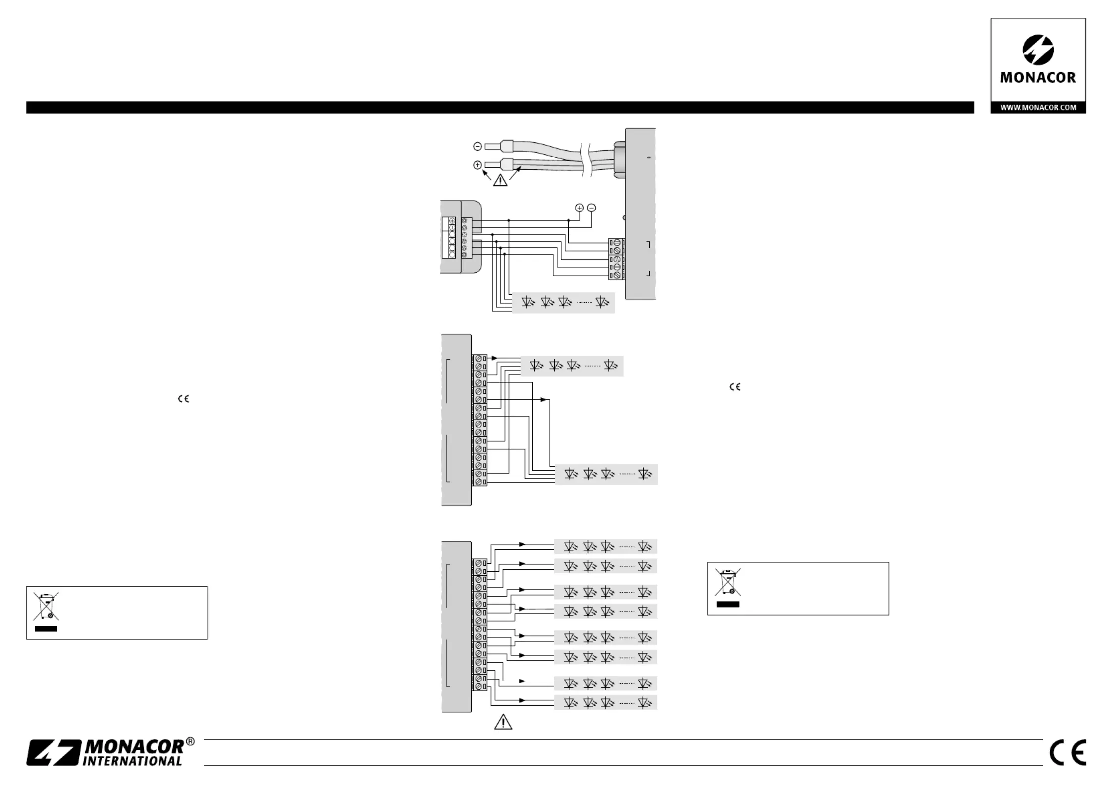
3 Connection
All terminals can be removed for easier
connection.
1) Connect the outputs of the controller
that are to be used for the LEDs to the
terminals INPUT of the CU-4BOOST:
Connect the outputs for Red, Green,
Blue and White to the input terminals
RED, GREEN, BLUE and WHITE and the
common positive pole to the terminal
+COM. As an example, figure 1 illus-
trates the connection of the controller
CU-4DMX.
2) Connect the LEDs to the terminals OUT-
PUT:
2 × WHITE = negative connections White
2 × RED = negative connections Red
2 × GREEN = negative connections Green
2 × BLUE = negative connections Blue
8 × +COM = positive connections
Always observe the following: The ma-
ximum power rating of each output
terminal is 10 A. The total power of the
CU-4BOOST, however, must not exceed
44 A.
As an example, figure 2 illustrates the
connection of 2 RGBW LED strips, and
figure 3 illustrates the connection of
8single-colour LED strips.
3) Use a regulated power supply unit for
power supply. The power supply unit
must be able to deliver the power re-
quired for operating the LEDs connected.
Set the power supply unit to the oper-
ating voltage of the LEDs (
⎓
12 Vmin.,
⎓
24 V max.). Connect the power supply
cable of the CU-4BOOST to the power
supply unit. Connect the marked core
to the of the power supply positive pole
unit! Once the operating voltage has
been applied, the LED POWER ON will
light up and the amplifier will be ready
for operation.
4 Specifications
Power rating: . . . . . 10 A max. for each
terminal,
a total of 44 A max.
Operating voltage: .
⎓
12 – 24 V (depend-
ing on the LEDs)
Connection cable: 1 m, 2 × 6 mm
2
Quiescent current: . 10 mA
Dimensions: . . . . . . 106 × 38 × 128 mm
Weight: . . . . . . . . . 460 g
Subject to technical modification
LED-Booster
Diese Anleitung richtet sich an An-
wender mit Grundkenntnissen in der
Elektronik. Bitte lesen Sie diese Anlei-
tung vor dem Betrieb gründlich durch
und heben Sie sie für ein späteres
Nachlesen auf.
1 Einsatzmöglichkeiten
Der Verstärker CU-4BOOST für 4 Farbka-
näle wird benötigt, wenn die Belastbarkeit
des verwendeten LED-Steuergeräts für
die anzuschließenden LED-Streifen oder
LED-Module nicht ausreicht. Er wird di-
rekt hinter das Steuergerät geschaltet. Die
LEDs müssen mit einer Betriebsspannung
zwischen
⎓
12 V und
⎓
24 V arbeiten und
das Steuergerät (z. B. CU-4DMX) mit einer
Pulsbreitenmodulation.
2 Wichtige Hinweise
Das Gerät entspricht allen relevanten Richt-
linien der EU und ist deshalb mit ge-
kennzeichnet.
•
Verwenden Sie das Gerät nur im Innen-
bereich und schützen Sie es vor Feuchtig-
keit und Hitze (zulässiger Einsatztempe-
raturbereich ).0 – 40 °C
•
Verwenden Sie zum Reinigen nur ein tro-
ckenes, weiches Tuch, niemals Chemika-
lien oder Wasser.
•
Wird das Gerät zweckentfremdet, falsch
angeschlossen, überlastet oder nicht
fachgerecht repariert, kann keine Haf-
tung für daraus resultierende Sach- oder
Personenschäden und keine Garantie für
das Gerät übernommen werden.
Soll das Gerät endgültig aus dem
Betrieb genommen werden, ent-
sorgen Sie es gemäß den örtli-
chen Vorschriften.
3 Anschluss
Alle Klemmen lassen sich zum leichteren
Anschließen abziehen.
1) -Die für die LEDs vorgesehenen Aus
gänge am Steuergerät mit den Klem-
men INPUT des CU-4BOOST verbinden:
die Ausgänge für Rot, Grün, Blau und
Weiß jeweils mit den Eingangsklem-
men RED, GREEN, BLUE und WHITE
und den gemeinsamen Pluspol mit der
Klemme +COM. Abbildung 1 zeigt als
Beispiel den Anschluss des Steuergeräts
CU-4DMX.
2) Die LEDs mit den Klemmen OUTPUT ver-
binden:
2 × WHITE = Minusanschlüsse Weiß
2 × RED = Minusanschlüsse Rot
2 × GREEN = Minusanschlüsse Grün
2 × BLUE = Minusanschlüsse Blau
8 × + COM = Plusanschlüsse
Beachten Sie unbedingt: Jede Ausgangs-
klemme ist mit max. 10 A belastbar. Die
Gesamtbelastung des CU-4BOOST darf
jedoch nicht höher sein als 44 A.
Abbildung 2 zeigt beispielhaft den An-
schluss von 2 RGBW-LED-Streifen und
Abbildung 3 den Anschluss von 8 Einzel-
farben-LED-Streifen.
3) -Für die Stromversorgung ein stabili
siertes Netzgerät verwenden. Es muss
den Strom liefern können, der für den
Betrieb der angeschlossenen LEDs be-
nötigt wird. Das Netzgerät auf die
Betriebsspannung der LEDs einstellen
(min.
⎓
12 V , max.
⎓
24 V). Das Strom-
versorgungskabel des CU-4BOOST mit
dem Netzgerät verbinden. Die gekenn-
zeichnete Adermit dem Pluspoldes
Netzgerätes verbinden! Sobald die Be-
triebsspannung anliegt, leuchtet die
LED POWER ON und der Verstärker ist
betriebsbereit.
4 Technische Daten
Belastbarkeit: . . . . je Klemme max. 10 A,
insgesamt max. 44 A
Betriebsspannung:
⎓
12 – 24 V (abhängig
von den LEDs)
Anschlusskabel: . 1 m, 2 × 6 mm
2
Ruhestrom: . . . . . . 10 mA
Abmessungen: . . . 106 × 38 × 128 mm
Gewicht: . . . . . . . . 460 g
Änderungen vorbehalten.
Deutsch
English
Produktspecifikationer
| Varumärke: | Monacor |
| Kategori: | Wifi-repeater |
| Modell: | CU-4BOOST |
Behöver du hjälp?
Om du behöver hjälp med Monacor CU-4BOOST ställ en fråga nedan och andra användare kommer att svara dig
Wifi-repeater Monacor Manualer

27 Augusti 2024
Wifi-repeater Manualer
Nyaste Wifi-repeater Manualer
18 Mars 2026
17 Mars 2026
13 Mars 2026
7 Februari 2026
7 Februari 2026
6 Februari 2026
6 Februari 2026
5 Februari 2026
2 Februari 2026
1 Februari 2026