NuTone 769RFT Bruksanvisning
NuTone hushålls fläkt 769RFT
Läs gratis den bruksanvisning för NuTone 769RFT (6 sidor) i kategorin hushålls fläkt. Guiden har ansetts hjälpsam av 43 personer och har ett genomsnittsbetyg på 4.8 stjärnor baserat på 3 recensioner. Har du en fråga om NuTone 769RFT eller vill du ställa frågor till andra användare av produkten? Ställ en fråga
Sida 1/6
BathroomExhaustFan/FluorescentLightCombination
MODEL:769RFT
VentiladordeEscape/Luzfluorescentedelbaño
MODELO:769RFT
FORBESTRESULTS
WheninstallingtheExhaustFan/Lightinanewconstruction
site,installhousingduringtherough-inconstructionofthe
building.Theblowerunitandgrilleshouldbeinstalledafterthe
finishedceilingisinplace.
ToinstalltheExhaustFan/Lightinanexistingfinishedbuilding
seeinstructionspage4.
IMPORTANTSAFETYINSTRUCTIONS
WARNING:TOREDUCETHERISKOFFIRE.
ELECTRICSHOCK,ORINJURYTOPERSONS,
OBSERVETHEFOLLOWING:
A.Usethisunitonlyinthemannerintendedbythe
manufacturer.Ifyouhavequestions,contactthe
manufacturer.
B.Beforeservicingorcleaningunit,switchpoweroff
atservicepanelandlockservicepaneltoprevent
powerfrombeingswitchedonaccidentally.
Whentheservicedisconnectingmeanscannotbe
locked,securelyfastenaprominentwarningdevice,
suchasatag,totheservicepanel.
CAUTION:
Forgeneralventilatinguseonly.Donotuseto
exhausthazardousorexplosivematerialsand
vapors.
INSTALLATIONINSTRUCTIONS
WARNING:TOREDUCETHERISKOFFIRE,
ELECTRICSHOCK,ORINJURYTOPERSONS,
OBSERVETHEFOLLOWING:
A.Installationworkandelectricalwiringmustbe
donebyqualifiedperson(s)inaccordancewithall
applicablecodesandstandards,includingfire-
ratedconstruction.
B.Sufficientairisneededforpropercombustionand
exhaustingofgasesthroughtheflue(chimney)of
fuelburningequipmenttopreventbackdrafting.
Followtheheatingequipmentmanufacturer's
guidelineandsafetystandardssuchasthose
publishedbytheNationalFireProtection
Association(NFPA),andtheAmericanSocietyfor
Heating,RefrigerationandAirConditioning
Engineers(ASHRAE),andthelocalcode
authorities.
C.Whencuttingordrillingintowallorceiling,donot
damageelectricalwiringandotherhiddenutilities.
D.Ductedfansmustalwaysbeventedtothe
outdoors.
E.Ifthisunitistobeinstalledoveratuborshower,it
mustbemarkedasappropriatefortheapplication.
F.NEVERplaceaswitchwhereitcanbereached
fromatuborshower.
•
WARNING:Toreducetheriskoffireorelectric
shock,donotusethisfanwithanysolid-state
speedcontroldevice.
•
Notforuseinkitchens.
•
Forinstallationinslopedceilingsupto12/12pitch.
•
Ductworkmustpointup.
•SUITABLEFORUSEOVERATUBOR
SHOWERWHENINSTALLEDINAG.F.C.I.
PROTECTEDBRANCHCIRCUIT.
•DONOTINSTALLINACEILINGINSULATED
TOAVALUEGREATERTHANR-40.
INSTALLATIONINSTRUCTIONS
READ&SAVETHESE
INSTRUCTIONS!
INSTRUCCIONESDEINSTALACIÓN
¡LEAYGUARDEESTAS
INSTRUCCIONES!
PARAMEJORESRESULTADOS
CuandoestáinstalandoelVentiladorExtractor/Luzenunsitiode
construcciónnuevo,instalelacubiertadurantelainstalaciónocultadel
inmueble.Launidaddelventiladorylarejilladebenserinstaladosdespués
dequeelcielorrasoseaacabado.
ParainstalarelVentiladorExtractor/Luzenuninmuebleacabado,vealas
instruccionesenlapágina4.
INSTRUCCIONESDESEGURIDAD
IMPORTANTES
ADVERTENCIA:PARAREDUCIRELRIESGODE
INCENDIO,DESCARGAELÉCTRICA,OHERIDASA
PERSONAS,OBSERVELOSIGUIENTE:
A.Useestaunidadcomoloindicaelfabricante.Sitiene
preguntas,contactealfabricante.
B.Antesdehacermantenimientoodelimpiarla
unidad,apagueelinterruptorenelpaneldeservicio
paraprevenirqueelinterruptorseprendapor
casualidad.Cuandolosmediosparadesconectarel
servicionosepuedanasegurar,sujeteunemblema
deadvertenciaprominente,talcomounaetiqueta,al
paneldeservicio.
ATENCIÓN:
Parausodeventilacióngeneralsolamente.Nousar
paraextraermaterialesovaporespeligrososo
explosivos.
INSTRUCCIONESDEINSTALACIÓN
ADVERTENCIA:RARAREDUCIRELRIESGODE
INCENDIO,DESCARGAELÉCTRICA,OHERIDASA
PERSONAS,OBSERVELOSIGUIENTE:
A.Eltrabajodeinstalacióneinstalacióneléctricadebe
serhechoporpersona(s)calificada(s)deacuerdo
contodosloscódigosynormasaplicables,
incluyendolaconstruccióndelíndicedefuego.
B.Suficienteaireesnecesarioparaladebida
combustiónyextraccióndegasesporelconducto
(chimenea)delequipoquequemacombustiblepara
prevenirquesedevuelvalacorrientedeaire.Sigala
guíayloscódigosdeseguridaddelfabricantede
equiposdecalefaccióntalescomolaspublicadas
porlaAsociaciónNacionaldeProteccióndeFuego
(NFPA),ylaAsociaciónAmericanaparaIngenieros
deCalefacción,RefrigeraciónyAireAcondicionado
(ASHRAE),ylasautoridadeslocales.
C.Cuandoestecortandootaladrandolaparedoel
techo,nolehagadañoaloscableseléctricosoa
otrasutilidadesescondidas.
D.Losventiladoresdeconductosiempredebenemitir
haciaafuera.
E.Siestaunidadsevaainstalarsobreunatinaouna
ducha,debesermarcadacomoapropiadaparaesta
aplicación.
F.NUNCApongauninterruptordondesepueda
alcanzardesdeunatinaounaducha.
•ADVERTENCIA:Parareducirelriesgode
incendioodescargaeléctrica,nouseeste
ventiladorconningúndispositivodecontrolde
velocidaddeestadosólido.
•Noesparausoenlacocina.
•Esparainstalaciónencielorrasosenpendientede
hasta12/12deinclinación.
•Lareddeconductosdebeapuntarparaarriba.
•APROPIADOPARAUSARSOBREUNATINAO
DUCHACUANDOSEINSTALAENUNARAMA
DECIRCUITOPROTEGIDODEA.G.F.C.I.
•NOINSTALEENUNCIELORRASOAISLADO
CONUNVALORMAYORAR-40.
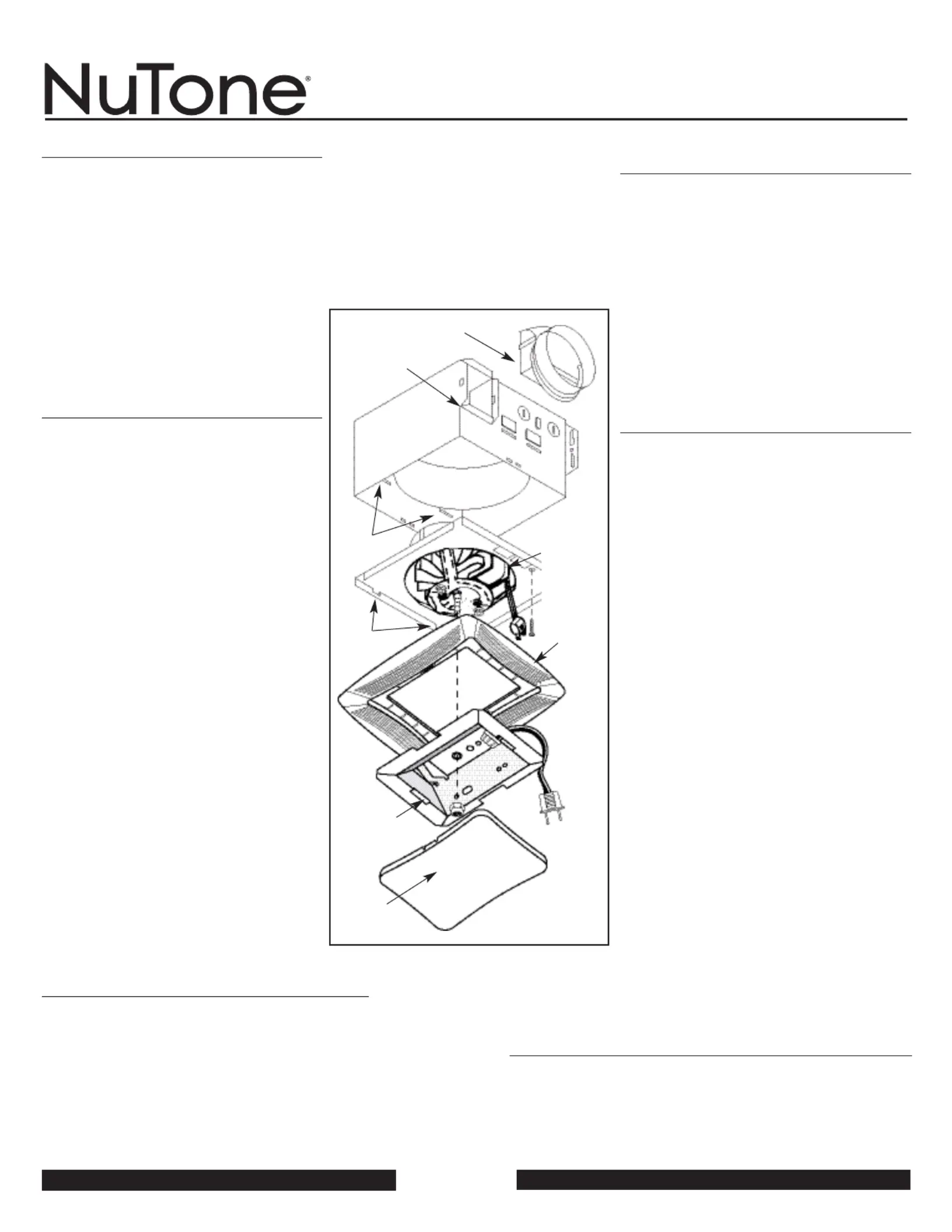
FIGURE1
D
UCTCOLLAR
COLLARDELDUCTO
HOUSING
CUBIERTA
SLOTS
RANURAS
TABS
LENGUETAS
GRILLE
PARRILLA
REFLECTOR
REFLECTOR
LENS
LENTE
POWER
UNIT/BLOWER
ASSEMBLY
ENSAMBLE
DELA
UNIDADE
POTENCIA/
VENTILADOR
TOREGISTERTHISPRODUCT,VISITWWW.NUTONE.COM
PARACOLOCARESTEPRODUCTO,VISITEWWW.NUTONE.COM
Produktspecifikationer
| Varumärke: | NuTone |
| Kategori: | hushålls fläkt |
| Modell: | 769RFT |
Behöver du hjälp?
Om du behöver hjälp med NuTone 769RFT ställ en fråga nedan och andra användare kommer att svara dig
hushålls fläkt NuTone Manualer

9 Augusti 2025
9 Augusti 2025
9 Augusti 2025
9 Augusti 2025
8 Augusti 2025
8 Augusti 2025
8 Augusti 2025
8 Augusti 2025
8 Augusti 2025
8 Augusti 2025
hushålls fläkt Manualer
Nyaste hushålls fläkt Manualer
1 April 2026
1 April 2026
26 Mars 2026
26 Mars 2026
25 Mars 2026
25 Mars 2026
24 Mars 2026
23 Mars 2026
22 Mars 2026
22 Mars 2026