Rademacher DuoFern Funksender UP 9497 Bruksanvisning
Rademacher
Smarth hem
DuoFern Funksender UP 9497
Läs gratis den bruksanvisning för Rademacher DuoFern Funksender UP 9497 (4 sidor) i kategorin Smarth hem. Guiden har ansetts hjälpsam av 23 personer och har ett genomsnittsbetyg på 3.7 stjärnor baserat på 12 recensioner. Har du en fråga om Rademacher DuoFern Funksender UP 9497 eller vill du ställa frågor till andra användare av produkten? Ställ en fråga
Sida 1/4

1. General safety information
3. Improper use
Never use the DuoFern radio system and its components for
the remote control of appliances and systems with increased
safety-relevant requirements or where there is an accident
risk. This shall require additional safety equipment. Observe
the respective statutory regulations for the installation of
such systems.
The use of defective equipment can lead
to personal injury and damage to prop-
erty.
Never use defective or damaged equipment.
Please contact our Customer Service depart-
ment in this event .
2. Proper use
Proper use
Only use the DuoFern flush-mounted radio transmitter for
the remote control of DuoFern devices such as:
◆DuoFern switch actuators
◆ DuoFern tubular motor actuators
◆DuoFern tubular motors or DuoFern belt winders, etc.
Operating conditions
◆Only use the DuoFern flush-mounted radio transmitter
in dry rooms.
◆The installation and operation of the DuoFern radio
system and its components (e.g. DuoFern tubular
motor actuator) is only permitted for systems and de-
vices where a malfunction in the transmitter or receiver
would not cause a danger to personnel or property or
where this risk is already covered by other safety equip-
ment.
4.2 Functional description
The DuoFern flush-mounted radio transmitter enables exist-
ing commercially available switches or switch systems to be
upgraded with DuoFern radio technology. Multiple DuoFern
actuators or other DuoFern devices can be controlled with
the help of the connected switch and switches can be re-
motely controlled once the DuoFern flush-mounted radio
transmitter has been registered in the DuoFern network.
In addition, control signals from movement sensors or win-
dow contacts can be used for control purposes.
The mode setting and input configuration is realised with
the help of the two selector switches . S1/S2
Battery com-
partment
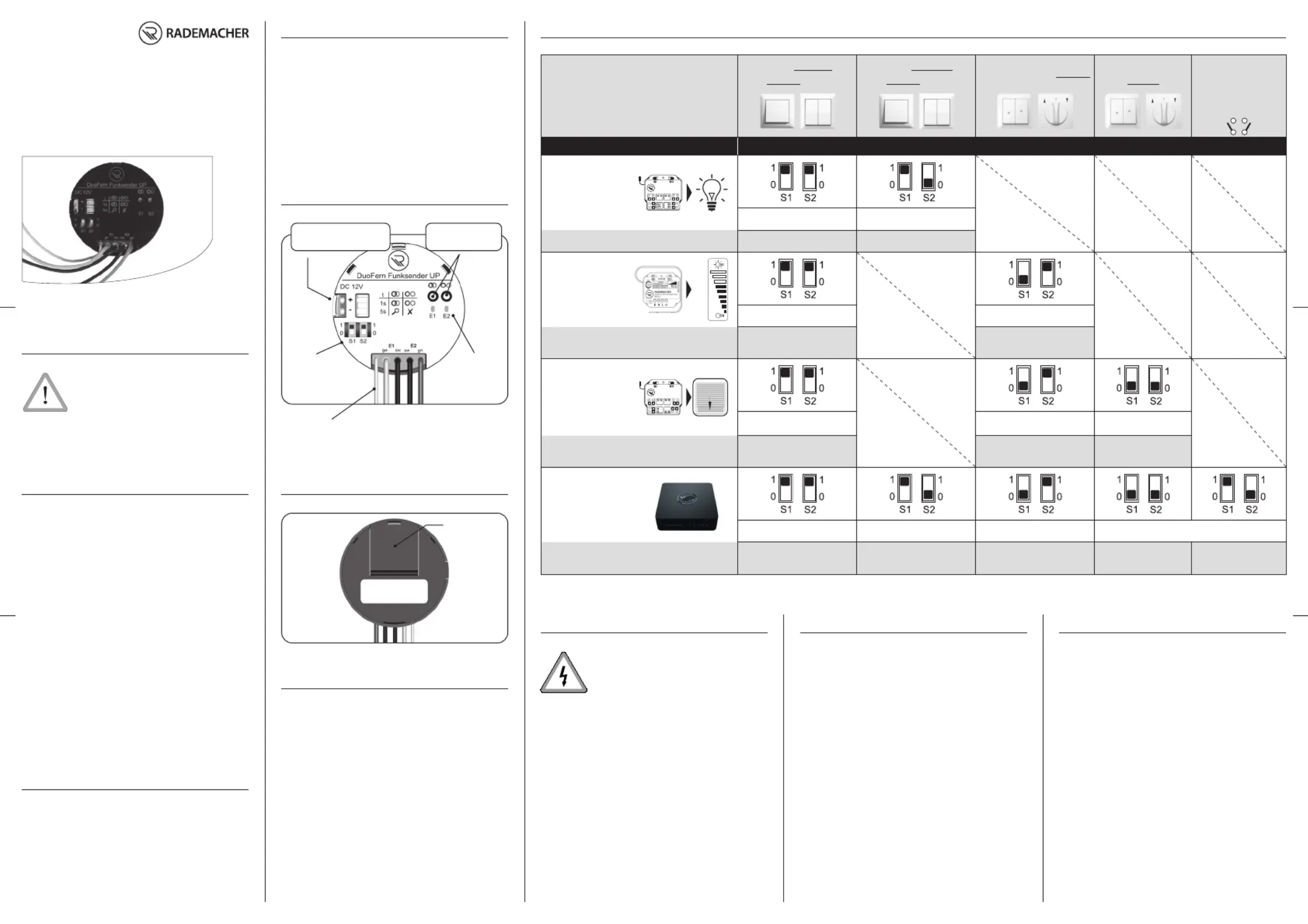
4.3 Configuration of the DuoFern radio transmitter and assignment of control commands
Connected
actuator
2 X SINGLE BUTTONS OR
1 X BUTTON IN SERIES
2 X SINGLE SWITCHES OR
1 X SWITCH IN SERIES
VENETIAN BLINDS BUTTON
VENETIAN BLINDS
SWITCH
SENSOR
FUNCTION *
(e. g. external
Window/Door Contact)
Applications Switch positions - S1 / S2
Switch actuator
e.g. DuoFern Universal
Actuator with
electrical appliance
Maximum 1 actuator per switch Maximum 16 actuators
Transmission > on / off on / off
Dimming actuator
e.g. DuoFern
Universal Dimmer
Maximum 1 actuator per switch Maximum 16 actuators
Transmission > on / stop / off / stop
Jog mode: light / dark
> 1 sec. on / off
Roller shutter /
Venetian blinds
actuators
e.g. DuoFern tubular
motor actuator
Maximum 1 actuator per switch Maximum 16 actuators Maximum 16 actuators
Transmission > up / stop / down / stop
Jog mode: up /down
> 1 sec. up / down
Up / Stop / Down
HomePilot®
Maximum 1 HomePilot® Maximum 16 HomePilot® Maximum 16 HomePilot® Maximum 16 HomePilot®
Transmission > Push on / off
Jog mode: up /down
> 1 sec. up / down
Up / Stop / Down Closed / Open
* Select this setting to use the DuoFern radio transmitter in HomePilot® as a sensor for „contact open / closed“.
4.1 General view - back
5.1 Installation procedure
1. If an additional mains-powered installation is
installed near the installation site. The mains
power must be deactivated prior to installation.
2. Electrical connection in accordance with chapter 7.
3. Register the DuoFern flush-mounted radio trans-
mitter in the DuoFern radio network, see chap-
ter 8.
4. Insert the DuoFern radio transmitter in the
flush-mounted box and lay the connecting cables
in the box.
ATTENTION ANTENNA CABLE
◆ Fit the antenna as straight as possible to ensure
the best possible reception.
5. Fit the connected potential-free button or switch.
6. Switch the mains power again back on again,
if necessary.
6. Dismantling
1. If an additional mains-powered installation is
installed near the installation site. The mains
power must be deactivated prior to disassembly.
2. Open the switch box.
3. Pull out the existing button / switch as well as
the DuoFern flush-mounted radio transmitter
from the switch box and disconnect them from
each other.
4. Restore the safe initial state of the switch
installation again.
4. General view - front
External power
supply 12 V / DC
Connect /
disconnect key
DIP switch
S1 / S2
Indicator LEDs
E1 / E2
Antenna (white) 4 x connecting leads:
E1 = ge + sw (yellow / black)
E2 = sw + gn (black / green)
Type plate
5. Assembly
During both installation and dismount-
ing of the DuoFern flush-mounted radio
transmitter there is a risk of fatal electric
shocks.
Observe the safety instructions for electrical
connection in chapter 7 prior to installation.
The DuoFern flush-mounted radio transmit-
ter is designed for flush-mounting only. We
recommend using a 58 mm deep box.
NOTE
In order to ensure optimal operation, the
DuoFern flush-mounted radio transmitter
should not be installed on a metallic base or
near metal objects.
Item No.: 3200 00 62
VBD 597-3 (01.20)
DuoFern radio transmitter 9497,
flush-mounted
Operating and Assembly Manual
3. Improper use
IMPORTANT
◆Do not install the DuoFern radio transmitter outside.
◆Never simultaneously connect / insert a battery and
external power supply. Doing so will damage the bat-
tery and may cause it to leak.
◆The connecting wires may not be extended.
RADEMACHER
STATUS
9470-1
DuoFern 1-Kanal Aktor
K
L
L
N N
E
Made in Germany
RADEMACHER
STATUS
9471-1
DuoFern Rohrmotor-Aktor
L N
▲
▼
L N
E
▲
▼
Made in Germany
0 %
100%

DuoFern Funksender UP
DC 12V
+
E1
E2
1
0
S1 S2
1
0
E1
ge gnsw sw
E2
t
1s
5s
14. Warranty conditions
RADEMACHER Geräte-Elektronik GmbH provides a 24-month warranty for
new systems that have been installed in compliance with the installation
instructions. All construction faults, material defects and manufacturing
defects are covered by the warranty.
Your statutory warranty claims shall remain unaffected by this warranty.
The following are not covered by the warranty:
◆Incorrect fitting or installation
◆Non-observance of the installation and operating instructions
◆Improper operation or wear and tear
◆External influences, such as impacts, knocks or weathering
◆Repairs and modifications by third party, unauthorised persons
◆Use of unsuitable accessories
◆Damage caused by unacceptable excess voltage (e.g. stroke of
lightning)
◆Operational malfunctions caused by radio frequency overlapping
and other such radio interference
A prerequisite for the warrant is that the new device must have been pur-
chased from one of our approved specialist retailers. Proof of this must be
provided by presenting a copy of the bill.
RADEMACHER shall remedy any defects, which occur within the warranty
period free of charge either by repair or by replacement of the affected
parts or by supply of a new replacement unit or one to the same value.
There is no general extension of the original warranty period by delivery of
a replacement or by repair as per the terms of the warranty.
RADEMACHER
Geräte-Elektronik GmbH
Buschkamp 7
46414 Rhede (Germany)
info@rademacher.de
www.rademacher.de
Service:
Hotline 01807 933-171*
Fax +49 2872 933-253
service@rademacher.de
* 30 seconds free of charge, subsequently 14 cents / minute
from German fixed line networks and max. 42 cents / minute
from German cellular networks.
Subject to technical modifications, misprints and errors.
Illustrations not binding.
Supply voltage
- with internal battery: 3 V DC
- with external connection: 12 V DC
Battery type: 3 V / CR 2032
Battery life:
- in normal operation approx. 12,000 control
commands
- in Standby: approx. 5 years
Transmission power: max. 10 mW
Range:
- in a building
(depending on construction): approx. 30 m
- outside: approx. 100 m
Transmission frequency: 434.5 MHz
Max. number of
DuoFern end units: 16
Permissible ambient
temperature range: + 5 °C to + 40°C
Dimensions (diameter x D): 50 x 11 (mm)
13. Technical Specifications7. Electrical connection
7.1 Connection of two buttons or switches
7.2 Connection of a Venetian blinds button or switch
Safety instructions
There is a risk of fatal electric shocks.
The electrical connection and all work on
electrical systems must only be carried out
by a qualified electrician in accordance with
the connection instructions in these operat-
ing instructions.
◆ Carry out all installation and connection
work only in an isolated, zero-volts state.
◆ Disconnect all phases of the lead from one
of the switch installations at the instal-
lation site and secure it to prevent any
reconnection.
◆ Check the system for a zero-voltage
status.
Connecting conditions:
Potential-free inputs E1 / E2:
Connection of mains voltage to inputs
E1 and E2 will create a short-circuit and
cause the DuoFern flush-mounted radio
transmitter to be damaged.
Only potential-free contacts (buttons or
switches) may be connected to inputs E1 / E2.
Input 12 V DC
Supply voltage: 12 V
Power: min. 0.5 W
You must assign the DuoFern radio transmitter to every
required DuoFern device in order that the DuoFern flush-
mounted radio transmitter can be used to control a DuoFern
actuator or other DuoFern device. In order to log-on and log-
off, press the corresponding button with a pointed (but not
sharp) object, for example, with a pen:
= connect button (log-in)
= disconnect button (log-off)
NOTE
Registering mode remains active for approx. 120 seconds.
8. Login of DuoFern end units
8.1 Registration of DuoFern
end units where S1 = 1
1. Switch the respective DuoFern end unit
to login mode (please refer to the rele-
vant operating instructions).
2. Briefly press the connect button on the
DuoFern flush-mounted radio transmit-
ter, both indicator LEDs E1 / E2 flash
green.
3. Indicator LEDs E1 and E2 additionally light up red
on successful registration.
4. In order to assign a channel to the DuoFern end unit
press the respective button / switch on input
E1 or E2.
4.1. In the event of multi-channel DuoFern end units
(e.g. DuoFern universal actuator) Point 4 repeat
for the next channel.
NOTE
If the current channel cannot be assigned for a DuoFern
actuator, please briefly press the disconnect.
8.2 Registration of DuoFern
end units where S1 = 0
1. Switch the respective DuoFern end
unit to login mode (please refer to the
relevant operating instructions).
2. Briefly press the connect button DuoFern
flush-mounted radio transmitter.
3. Observe the respective indicator LED E1 / E2:
Green: Login was successful.
Red: Login failed.
8.3 Logging-out DuoFern end units
1. Switch the respective DuoFern end unit
to logout mode (please refer to the
relevant operating instructions).
2. Briefly press the disconnect button on
the DuoFern flush-mounted radio trans-
mitter.
3. Observe the respective indicator LED E1 / E2:
Green: Log off was successful.
Red: Log off failed.
NOTE
All of the channels of the DuoFern actuator are logged-
off simultaneously.
9. Clear
This function logs off all of the registered DuoFern end units
that no longer react. This could be necessary with a faulty
unit, for instance, that can no longer be logged off, as de-
scribed previously in chapter 8.3.
NOTE
◆Battery-operated DuoFern devices cannot be logged
off in this way. They must be logged-off by resetting,
see chapter 10.
1. Press and hold the connect button for
approx. 5 seconds until both indicator
LEDs E1 / E2 flash.
2. The DuoFern flush-mounted radio transmitter
now transmits a control signal to all registered
DuoFern end units.
Unavailable DuoFern end units are automatically
logged-off.
3. Clearing is complete as soon as the indicator LEDs
E1 / E2 light up continuously green.
10. Deleting all settings (Reset)
1. Press and hold the disconnect button
until both indicator LEDs E1 / E2 light up
red.
2. All connections will be deleted. The DuoFern flush-
mounted radio transmitter is now returned to its
original factory condition.
11. Battery replacement
1. -Open the battery compartment cover and care
fully slide the battery out of the compartment,
for example, using a thin pen.
2. Replace the battery with a new one of the same
type (CR 2032).
IMPORTANT
When inserting the battery, pay attention to the cor-
rect polarity. The position of the negative terminal is
labelled on the battery compartment.
3. Close the battery compartment again until you
hear it click into place.
NOTE
Empty batteries are special waste and should not be
disposed of with household waste.
Antenna (white)
Up Stop Down
Antenna (white)
8.1 Registration of DuoFern
end units where S1 = 1
5. Observe the respective
E1 or E2:
Green: Login was successful.
Red: Login failed.
12. Simplified EU Declaration of Conformity
RADEMACHER Geräte-Elektronik GmbH hereby
declares that the DuoFern radio transmitter
9497 flush-mounted complies with the Directive
2014/53/EU (Radio Equipment Directive).
The full text of the declaration of conformity is
available at the following website:
www.rademacher.de/ce
Produktspecifikationer
Varumärke: | Rademacher |
Kategori: | Smarth hem |
Modell: | DuoFern Funksender UP 9497 |
Färg på produkten: | Wit |
Vikt: | 34 g |
Bredd: | 46 mm |
Djup: | 18 mm |
Höjd: | 59 mm |
Snäll: | Elektronische hygrometer |
Husmaterial: | Kunststof |
Kraftkälla: | Batterij/Accu |
Placering: | Table, Wall |
Måttenhet temperatur: | F, °C |
Antal batterier/batterier som stöds: | 1 |
Avsedd för: | Binnen |
Termometer: | Ja |
Temperaturmätningsområde: | -50 - 70 °C |
Batterier-ingår: | Ja |
Type beeldscherm: | Digitaal |
Batterityp: | CR2032 |
Skärmstorlek: | Rechthoekig |
Temperature measurement range: | -58 - 158 °F |
Meetbereik vochtigheid: | 10 - 99 procent |
Behöver du hjälp?
Om du behöver hjälp med Rademacher DuoFern Funksender UP 9497 ställ en fråga nedan och andra användare kommer att svara dig
Smarth hem Rademacher Manualer
5 Januari 2025
13 Augusti 2024
28 Juli 2024
Smarth hem Manualer
- Athom
- SPC
- Nous
- Homematic IP
- Logicom
- Honeywell
- Bosch
- Osram
- Gardena
- Rain Bird
- Inkbird
- Hager
- Crestron
- Qnect
- Nexa
Nyaste Smarth hem Manualer
29 Mars 2025
29 Mars 2025
29 Mars 2025
27 Mars 2025
18 Mars 2025
18 Mars 2025
12 Mars 2025
26 Februari 2025
19 Februari 2025
18 Februari 2025