Rane FAC 24 Bruksanvisning
Rane ej kategoriserat FAC 24
Läs gratis den bruksanvisning för Rane FAC 24 (4 sidor) i kategorin ej kategoriserat. Guiden har ansetts hjälpsam av 7 personer och har ett genomsnittsbetyg på 4.1 stjärnor baserat på 5 recensioner. Har du en fråga om Rane FAC 24 eller vill du ställa frågor till andra användare av produkten? Ställ en fråga
Sida 1/4
OPERATING / SERVICE MANUAL
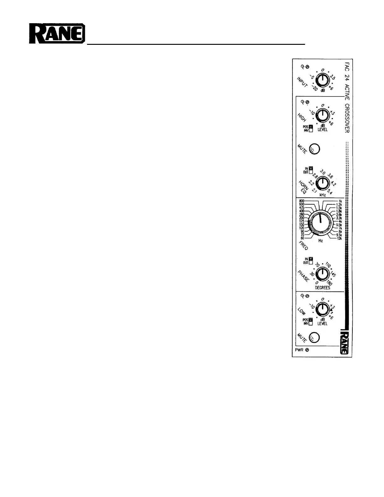
FAC 24/28
using a constant-directivity horn, set the “HORN EQ IN OUT” switch to the “IN” position and ad-
just the frequency control per the recommendations of the horn’s manufacturer. Set the “PHASE
IN OUT” switch to the “OUT” position. Set the crossover frequency selector to the frequency
recommended by the speaker manufacturer. Power up the system and set the input and output
levels for appropriate performance.
NEVER CONNECT ANYTHING EXCEPT AN APPROVED RANE POWER SUPPLY TO
THE THING THAT LOOKS LIKE A TELEPHONE JACK ON THE REAR OF THE FAC
24/28. This is an AC input and requires special attention if you do not have an operational power
supply EXACTLY like the one that was originally packed with your unit. See the full explanation
of the power supply requirements elsewhere in this manual.
It is a good idea to begin with all level controls set to their full counterclockwise position. Un-
less you are certain that there is an electrical inversion in one of your amplifiers or drivers, set
both “POS INV” switches to their “POS” positions. Both mute switches should be “out”. If you arc
the use of a FAC 24/28.
QUICK START
No one likes to read manuals. Everyone likes to plub in and turn on. That’s usuallv OK and
with only a very few exceptions, damage is unlikely to result from such procedures when initiating
SYSTEM CONNECTION
When connecting the FAC 24/28 to other components in your system for the first time, LEAVE
THE POWER SUPPLY FOR LAST. This will give you a chance to make mistakes and correct
them before any damage is done to your fragile speakers, ears and nerves.
INPUTS on the FAC 24/28 are balanced. The 3-pin (XLR) uses pin 2 as “hot” or “+” signal
polarity, pin 3 is “return” or “–” and pin 1 is signal ground. If unbalanced operation is required, drive
pin 2 as hot and pin 1 as ground. The l/4" input is a tip-ring-sleeve connector. Tip is (+), ring is (–),
and sleeve is ground. Unbalanced l/4" inputs should drive tip as hot and sleeve as ground and may
be either a “mono” l/4" or TRS l/4" with the ring left open or tied to sleeve, your choice. See Rane
Note 110 for further information on this subject.
OUTPUTS. The FAC 24/28's outputs are balanced as well. As with the 3-pin input, pin 2 is hot
and pin 3 is not. Pin 1 is signal ground. True balanced operation requires only the use of pins 2 and
3 for signal and either cast ground (chassis) or pin 1 signal ground for shielding. If unbalanced out-
put is your preference, use pin 2 as signal and pin 1 as return. Use case ground for shield. The l/4"
output is a tip-ring-sleeve character whose polarities match the input connector. Again, have a look
at Rane Note 110 for more detail.
THE LOW SUM INPUTis used to combine the low frequency outputs of two crossover
modules
(mono sub bass in stereo applications). To take advantage of this feature, the low frequency output
of one crossover module connects to this input (unbalanced only). The sum of both modules low frequency sections then ap-
pears at the low frequency output of the module whose low sum input is being driven.
3-WAY, 4-WAY etc. Two or more FAC crossovers may be used together to produce 3, 4 and S-way systems. To accomplish
this, the first unit is driven with full range audio. The Sub bass output is taken from the low out of the first module, the high
out of the first module then drives the main input of the second. For 3-way applications, mid and high are taken from the low
and high outs of the second module, respectively. If a four way system is being constructed, the high out of the second
module drives the third, the low out of the second module becomes the low-mid, the low out of the third module is the 3rd
frequency range, the high out of the third module becomes the 4th. See the diagram on the back page of this document as
well as the Flex User’s Guide for more details.
CHOICES need to be made regarding which input and output connectors to use. Generally, the l/4" ins and outs work well
enough and are definitely cheaper to use in terms of the labor required to terminate cables with 1/4" plugs and the material
cost. The 3-pins do, however, provide a locking mechanism for situations where physical abuse can be a problem. The 3-pin
also provides a tighter connection and can be more impervious to corrosion and stresses of time and environment.
Produktspecifikationer
| Varumärke: | Rane |
| Kategori: | ej kategoriserat |
| Modell: | FAC 24 |
Behöver du hjälp?
Om du behöver hjälp med Rane FAC 24 ställ en fråga nedan och andra användare kommer att svara dig
ej kategoriserat Rane Manualer

11 September 2025
11 September 2025
10 September 2025
10 September 2025
10 September 2025
10 September 2025
10 September 2025
10 September 2025
10 September 2025
10 September 2025
ej kategoriserat Manualer
Nyaste ej kategoriserat Manualer
3 April 2026
3 April 2026
3 April 2026
3 April 2026
3 April 2026
3 April 2026
3 April 2026
3 April 2026
3 April 2026