Reelcraft D83075 OLP Bruksanvisning


Läs gratis den bruksanvisning för Reelcraft D83075 OLP (12 sidor) i kategorin trädgårds slang. Guiden har ansetts hjälpsam av 2 personer och har ett genomsnittsbetyg på 4.9 stjärnor baserat på 1.5 recensioner. Har du en fråga om Reelcraft D83075 OLP eller vill du ställa frågor till andra användare av produkten? Ställ en fråga

Sida 1/12
Personal injury and/or equipment damage
may result if proper safety precautions are
not observed.
Ensure that reel is properly installed
before connecting input and output
hoses.
Bleed fluid/gas pressure from system
before servicing reel.
Before connecting reel to supply line,
ensure that pressure does not exceed
maximum working pressure rating of
Remember, even low pressure is very
dangerous and can cause personal in-
jury or death.
Be aware of machinery and personnel
in work area.
If a leak occurs in the hose or reel, re-
move system pressure immediately.
A high tension spring assembly is con-
tained within the reel. Exercise extreme
caution.
Pull hose from reel by grasping the
hose itself, not the control valve.
If reel ceases to unwind or rewind,
remove system pressure immediately.
Do not pull or jerk on hose!
Treat and respect the hose reel as any
other piece of machinery, observing all
common safety practices.
Operating Instructions
Series D80000 Spring Driven Hose Reels
Low and Medium Pressure Model Numbers:
Reelcraft Industries, Inc. 2842 E Business Hwy 30, Columbia City, IN 46725
Ph: 800-444-3134 / 260-248-8188 Fax: 800-444-4587 / 260-248-2605
Customer Service: 855-634-9109 reelcraft@reelcraft.com www.reelcraft.com
Form# 998-1099 Rev: 11/2019
D83000 OLP FD83000 OLP D83075 OLP-HTH
D83075 OLP FD83075 OLP D84050 OLP-HTH
D84000 OLP FD84000 OLP D84000 OMP
D84035 OLP FD84035 OLP D84050 OMP
D84050 OLP FD84050 OLP
Personal Safety
IMPORTANT
Read this manual carefully before installing,
operating or servicing this equipment.
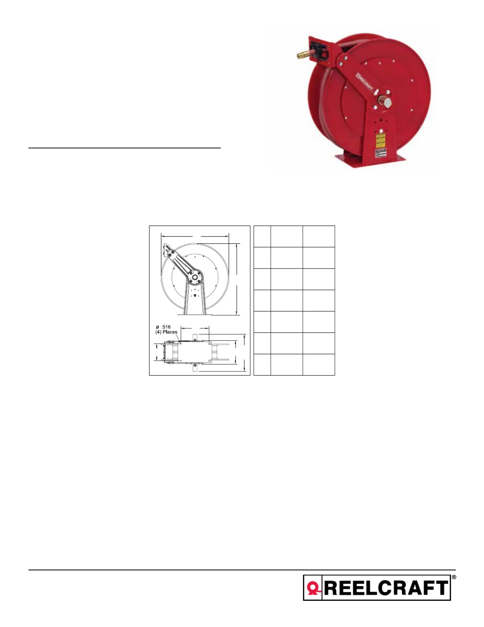
Dimensional Data
83000 84000
A25.375” 25.375”
B24” 24”
C10.5” 10.5”
D7.875” 7.875”
E13” 15.75”
F10.375” 10.375”
A
B
C
D
E
F
Series D80000 Spring Driven Hose Reels
Page 2
www.reelcraft.com
INSTALLATION INSTRUCTIONS
WARNING: Ensure that reel, hose, and
equipment are properly grounded. Use an
ohmmeter to check ground continuity.
Mounting
CAUTION: Unless reel was specified different-
ly when ordering, maximum installation height
is 16 feet. Do not exceed this distance.
1. Unpack and inspect reel for damage.
Turn by hand to check for smooth opera-
tion. Check for completeness.
2. Configure reel for top, side or bottom
hose dispensing by removing the bolts
(2) from one side of the guide roller
bracket and loosening the four guide arm
bolts (3) on each side of the hose reel.
Rotate and remove each guide arm then
reinstall in the desired configuration. If
bottom wind is desired, bolts (13) and
bolts (2) must be removed and replaced
after the guide arm is in position.
CAUTION :When changing guide arm
positions, the U-bolt must be placed in the
proper location as instructed in figure A. The
reel can “latch out” during use if this instruc-
tion is not adhered to.
3. Position reel on floor, wall, or ceiling.
Secure into place using four (customer
supplied) bolts.
Installing the Input Hose
WARNING: Ensure that supply line pressure
does not exceed maximum working pressure
rating of reel. Apply pipe thread sealant to all
threads on standard reels. Do not overtighten
connection. Recommended torque not to
exceed 70 ft. lb.
CAUTION: Use flexible hose connection at
input. Do not use rigid plumbing.
1. -Apply thread sealant as directed and con
nect swivel (12) to main shaft input (5).
2. -For standard shaft and swivel reels, con
nect customer supplied inlet hose (4) to
swivel input as indicated in illustration.
Installing the Output Hose
WARNING: Use extreme caution; reel under
tension. Avoid releasing latch mechanism.
CAUTION: Apply pipe thread sealant to all
threads on standard reels. Do not overtighten
connection. Recommended torque not to
exceed 70 ft. lb.
1. Manually turn sheave (6) until spring is
tight, back off 3 turns, then latch.
2. Route output hose (7) through roller
bracket (1), U-bolts (8), then through
cutout (9) in spool as indicated in illus-
tration.
3. Connect output hose (7) to gooseneck
(10) as indicated in illustration.
4. Verify U-bolt position conforms with
guide arm position using label inside
spool. Then tighten nuts (11) on U-bolt
(8).
5. Charge hose. Momentarily open control
valve to purge hose of gases. When fluid
appears at control valve, close valve.
With hose fully charged, release latch and
wind output hose onto reel.
6. Install bumper stop assembly.
ADJUSTMENTS
WARNING: Use extreme caution; reel under
tension. Avoid releasing latch mechanism.
If necessary, adjust spring tension on reel by
manually adding or removing wraps of hose
from spool, one wrap at a time, until desired
tension is obtained. Manually add wraps to
increase tension. Remove wraps to decrease
tension.
WARNING: Rewind hose on reel, then bleed
pressure from system before performing the
following procedures.
CAUTION: Remove all spring tension before
disassembling the hose reel. Do not attempt to
open the riveted spring case assembly.
1. -Replace hoses in accordance with proce
dures given in “Installation Instructions”
section of this manual.
2. -All mating moving parts have been fac
tory lubricated as required.
Figure A
Series D80000 Spring Driven Hose Reels
www.reelcraft.com
Page 3
ITEM DESCRIPTION QTY D83000 OLP D83075 OLP D84000 OLP D84035 OLP D84050 OLP FD83000 OLP FD83075 OLP
1 Swivel assembly 1 S602026 S602026 S600682 S600682 S600682 S602026-2 S602026-2
2 5/16-18 x 1/2” flange screw 4 * * * * * * *
3 Guide arm 2 261299 261299 261299 261299 261299 261299 261299
4 Spring & case assembly 1 S600645-3 S600645-3 S600645-3 S600645-3 S600645-3 S600645-3 S600645-3
5 U-bolt 1 * * * * * * *
6 5/16-18 locknut 6 * * * * * * *
7 Roller bracket assembly 1 S600705 S600705 S600705 S600705 S600705 S600705 S600705
9 1/4-20 locknut 9 * * * * * * *
10 Hose assembly 1 None S601034-75 None 601027-35 S601027-50 None S600160-3
11 Bumper stop assembly 1 None None 4-HR1005 4-HR1005 None3-HR1004-3 3-HR1004-3
12 3/8-16 x 5/8” screw 9 * * * * * * *
13 1 3/8” snap ring 2 * * * * * * *
14 Flange w/bearing & nut-sert 1 S600651 S600651 S600651 S600651 S600651 S600651 S600651
15 Ratchet, flow casting 1 S261590-1 S261590-1 261591-1 261591-1 261591-1 S261590-1 S261590-1
16 Spool spacer 1 261393 261393 261393 261393 261393 261393 261393
17 1/2-20 x 5/8” hex nut 1 * * * * * * *
18 3/8-16 hex nut 1 * * * * * * ***
18 10-32 Nyloc nut 1 * * * * * * *
19 Base & upright assembly 1 600704 600704 600704 600704 600704 600704 600704
20 Latch spring stud 1 261351 261351 261351 261351 261351 261351 261351**
20 Shoulder screw 1 S393-2 S393-2 S393-2 S393-2 S393-2 S393-2 S393-2
21 Latch spring 1 260067-1 260067-1 260067-1 260067-1 260067-1 260067-1 260067-1
22 Latch pawl assembly 1 S600018 S600018 S600018 S600018 S600018 S600018 S600018
23 Bearing & flange assembly 1 S600644 S600644 S600644 S600644 S600644 S600644 S600644
24 Sheave, hose opening 1 261307 261307 261307 261307 261307 261307 261307
25 Pipe plug 1 S183-54 S183-54 261396 261396 261396 S183-54 S183-54
26 Sheave, springcase 1 261308 261308 261308 261308 261308 261308 261308
27 Screw, 1/4-20 x 2 1/2” 8 S2-411 S2-411 S2-411 S2-411 S2-411 S2-411 S2-411
28 Screw, 5/16-18 x 2 1/2” 3 S2-511 S2-511 S2-511 S2-511 S2-511 S2-511 S2-511
--- Maximum pressure -- 500 PSI 250 PSI 500 PSI 250 PSI 250 PSI 500 PSI 50 PSI
--- Maximum temperature -- 210 °F 150 °F 210 °F 150 °F 150 °F 210 °F 150 °F
*Included in hardware kit part number 600654
**Prior to March 2012


Produktspecifikationer

Varumärke: Reelcraft
Kategori: trädgårds slang
Modell: D83075 OLP

Behöver du hjälp?

Om du behöver hjälp med Reelcraft D83075 OLP ställ en fråga nedan och andra användare kommer att svara dig