Reelcraft TH88000 OMP Bruksanvisning
Reelcraft trädgårds slang TH88000 OMP
Läs gratis den bruksanvisning för Reelcraft TH88000 OMP (9 sidor) i kategorin trädgårds slang. Guiden har ansetts hjälpsam av 28 personer och har ett genomsnittsbetyg på 4.2 stjärnor baserat på 4 recensioner. Har du en fråga om Reelcraft TH88000 OMP eller vill du ställa frågor till andra användare av produkten? Ställ en fråga
Sida 1/9
SAFETY
Personal injury and/or equipment damage may result if proper
safety precautions are not observed.
• Ensure that reel is properly installed before connecting input and
output hoses.
• Bleed fluid/gas pressure from system before servicing reel.
• Before connecting reel to supply line, ensure that pressure does
not exceed maximum working pressure rating of reel.
• Remember, even low pressure is very dangerous and can cause
personal injury or death.
• Be aware of machinery and personnel in work area.
• If a leak occurs in the hose or reel, remove system pressure
immediately.
• A high tension spring assembly is contained within the reel.
Exercise extreme caution.
• Pull hose from reel by grasping the hose itself, not the control
valve.
• If reel ceases to unwind or rewind, remove system pressure
immediately. Do not pull or jerk on hose!
• Treat and respect the hose reel as any other piece of machinery,
observing all common safety practices.
Operating Instructions
Reelcraft Industries, Inc. • 2842 E Business Hwy 30, Columbia City, IN 46725
Ph: 800-444-3134 / 260-248-8188 • Fax: 800-444-4587 / 260-248-2605
Customer Service: 855-634-9109 • [email protected] • www.reelcraft.com
Form# 964-998 Rev: 8/2018
Read this manual carefully before installing, operating or
servicing this equipment.
IMPORTANT
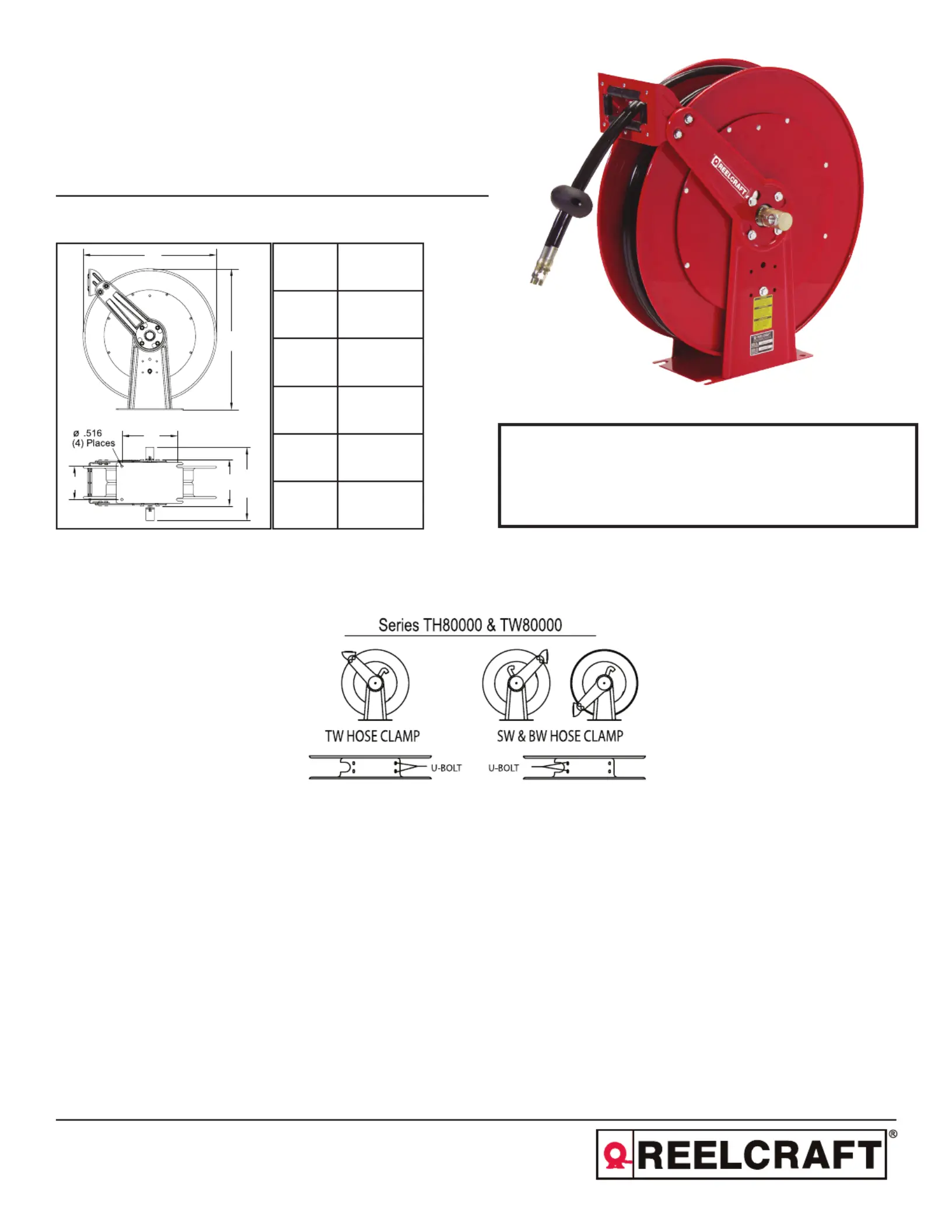
Dimensions
Series TH80000 Spring Driven Hose Reels
Figure A
TH86050 OMPTH86000 OMP
TH88050 OMPTH88000 OMP
A25 3/8”
B24”
C10”
D6”
E12 7/8”
F8 1/8”
A
B
C
D
E
F
Produktspecifikationer
| Varumärke: | Reelcraft |
| Kategori: | trädgårds slang |
| Modell: | TH88000 OMP |
Behöver du hjälp?
Om du behöver hjälp med Reelcraft TH88000 OMP ställ en fråga nedan och andra användare kommer att svara dig
trädgårds slang Reelcraft Manualer

3 Februari 2026
1 Februari 2026
1 Februari 2026
31 Januari 2026
30 Januari 2026
30 Januari 2026
30 Januari 2026
29 Januari 2026
21 September 2025
20 September 2025
trädgårds slang Manualer
Nyaste trädgårds slang Manualer
7 Mars 2026
25 September 2025
22 September 2025
22 September 2025
22 September 2025
22 September 2025
22 September 2025
22 September 2025
20 September 2025
11 September 2025