Robbe 1-F1666 Bruksanvisning
Robbe Radiostyrda leksaker 1-F1666
Läs gratis den bruksanvisning för Robbe 1-F1666 (48 sidor) i kategorin Radiostyrda leksaker. Guiden har ansetts hjälpsam av 30 personer och har ett genomsnittsbetyg på 4.6 stjärnor baserat på 9 recensioner. Har du en fråga om Robbe 1-F1666 eller vill du ställa frågor till andra användare av produkten? Ställ en fråga
Sida 1/48
Instructions,
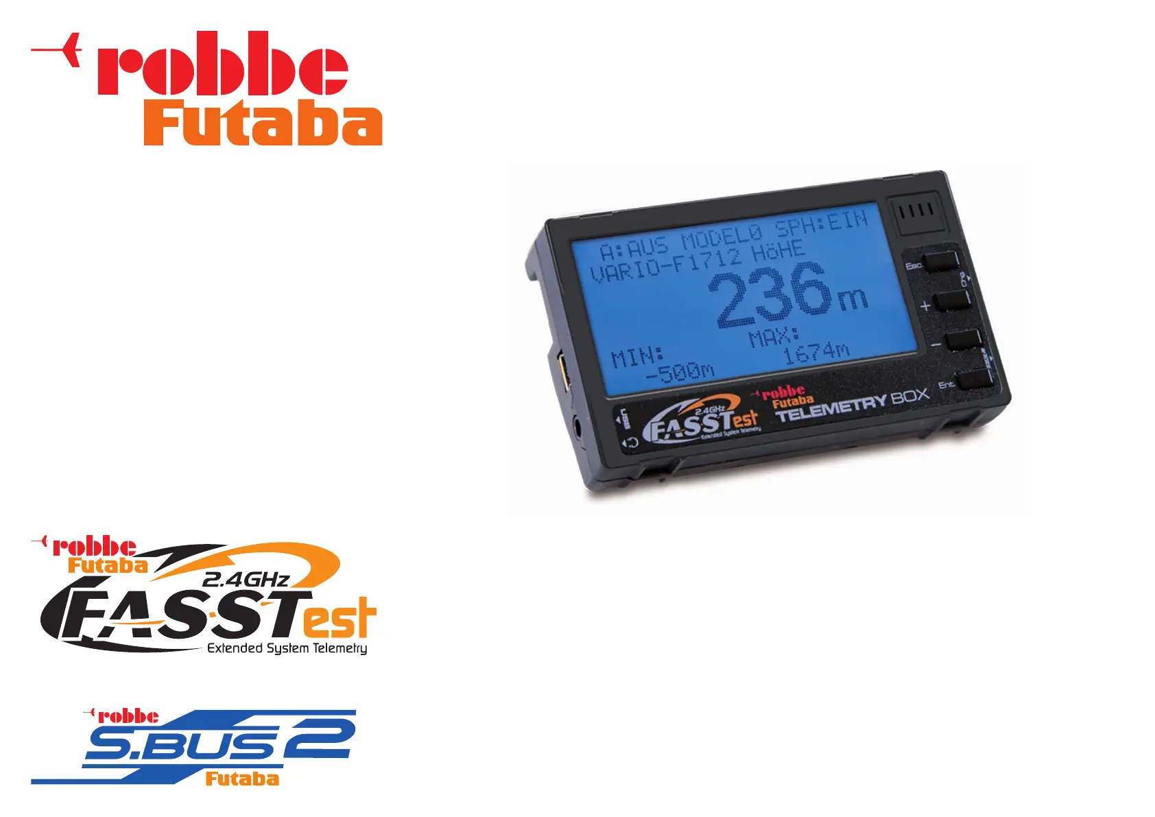
Telemetry-Box 2.4 GHz FASSTest
®
No. F1666
Produktspecifikationer
| Varumärke: | Robbe |
| Kategori: | Radiostyrda leksaker |
| Modell: | 1-F1666 |
Behöver du hjälp?
Om du behöver hjälp med Robbe 1-F1666 ställ en fråga nedan och andra användare kommer att svara dig
Radiostyrda leksaker Robbe Manualer

30 Mars 2025
30 Mars 2025
27 Mars 2025
20 September 2024
20 September 2024
20 September 2024
20 September 2024
20 September 2024
20 September 2024
20 September 2024
Radiostyrda leksaker Manualer
Nyaste Radiostyrda leksaker Manualer
2 April 2026
30 Mars 2026
28 Mars 2026
15 Mars 2026
23 Februari 2026
27 September 2025
13 September 2025
13 September 2025
12 September 2025
12 September 2025