Roland V-Drums TD516 Bruksanvisning
Roland ej kategoriserat V-Drums TD516
Läs gratis den bruksanvisning för Roland V-Drums TD516 (2 sidor) i kategorin ej kategoriserat. Guiden har ansetts hjälpsam av 18 personer och har ett genomsnittsbetyg på 4.7 stjärnor baserat på 9 recensioner. Har du en fråga om Roland V-Drums TD516 eller vill du ställa frågor till andra användare av produkten? Ställ en fråga
Sida 1/2
*5100093014-02*
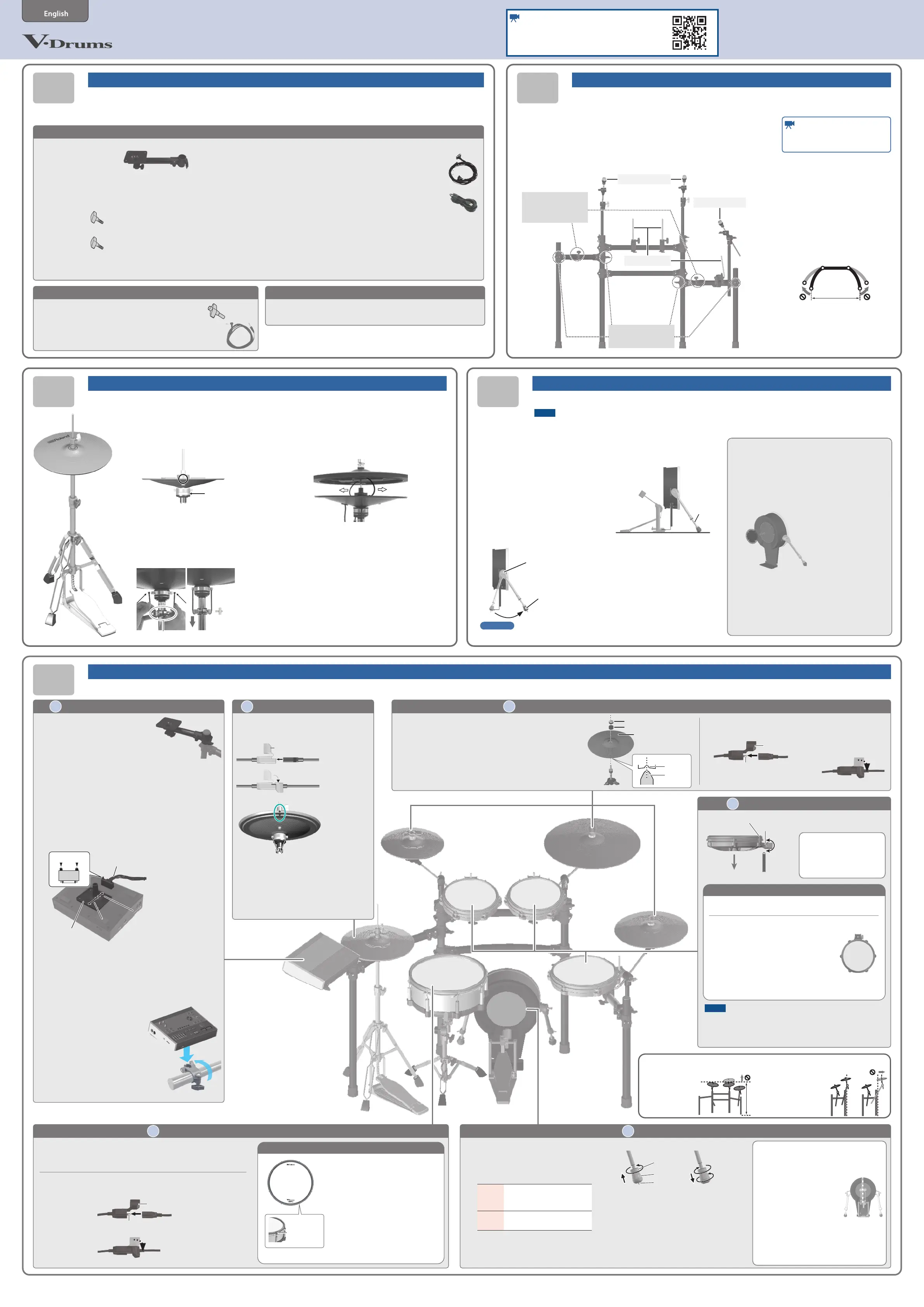
Attach the parts
0101
0303
0505
0404
33
Attach the crash cymbal (CY-12C-T / CY-14R-T) and ride cymbal (CY-18DR)
TD516
¹V51 (Drum sound module) x 1
–Sound module
mounting plate set x 1
¹PD-140DS (Digital snare) x 1
¹CY-18DR (Digital ride) x 1
¹VH-14D (Digital hi-hat) x 1
¹PD-10P (V-Pad for tom 1, 2) x 2
–Knob bolt
¹PD-12P (V-Pad for tom 3) x 1
–Knob bolt
¹CY-12C-T (V-Cymbal for crash 1) x 1
¹CY-14R-T (V-Cymbal for crash 2) x 1
Owner’s Manuals
¹TD516 Setup Guide (this document)
¹V51 Quick Start
–Roland Cloud Connect
Setup Guide
¹PD-140DS Owner’s Manual
¹CY-18DR Owner’s Manual
¹VH-14D Owner’s Manual
¹PD-12P/PD-10P Owner’s Manual
¹CY-14R-T/CY-12C-T Owner’s Manual
For details on each component, refer to the respective owner’s manual.
Check the included items
As soon as you open the package, check to see that all items are included. If anything is missing,
please contact your dealer.
* A Phillips screwdriver (#2) is required to assemble this product, available separately.
* This package does not include a kick pedal, a hi-hat stand, and a snare stand.
Use with a commercially available kick pedal, hi-hat stand, and snare stand.
Assembling the kick (KD-12)
MDS-Standard3KD-12 (Kick pad)
* For the items included with the stand (MDS-Standard3), refer to the
owner’s manual when checking that all items are included.
¹KD-12 (Kick Pad) x1
¹KD-12 Owner’s Manual
–Kick drum patch
–Anti-slip sheet
¹Drum Key × 1
¹Trigger cable
(Crash 2)
Assemble the hi-hat (VH-14D)
Assemble the hi-hat using the procedure described in “VH-14D Owner’s Manual”.
Adjusting the position
of the cymbal
* Adjust the cymbal positions as shown below, as it is very
dangerous if the stand falls over.
Adjust the height of the
rod so that the highest
point of the cymbal is
less than 1.2 meters.
Attach the cymbal so that
its center does not extend
toward the back beyond the
pipes of the stand (the pipes
at the back of the stand).
22
Attach the toms (PD-10P/PD-12P)
Adjusting the head tension
Adjust the tension so that the pad responds to your strikes
with the appropriate feel.
1. Adjust each tuning bolt little
by little, across the head as
indicated in the illustration.
2. Adjust the tightness of each
tuning bolt so that the head is
tensioned evenly.
* Before using the pad, tighten the head so that the tension
is rather rm.
Cables
¹Dedicated connection cable x 1
(Packed with the V51)
¹Connection cable x 3
(Packed in the respective
cartons of the PD-140DS,
CY-18DR, and VH-14D)
* V51, PD-12P, PD-10P, PD-140DS, CY-18DR,
and VH-14D accessories are in the
respective packing cartons.
11
Installing the kick (KD-12)
NOTE
Adjusting the head tension aects only the head response, and
does not change the pitch of the sound as it would on an acoustic
drum. Pitch adjustments are made by editing the sound in your
drum sound module. For details, refer to the “V51 Quick Start”.
55
Setting up the hi-hat (VH-14D)
Insert the plug of the connecting cable included
with the VH-14D into the DIGITAL TRIGGER OUT jack
of the VH-14D.
Connection cable
Protector
Use the protector to lock the
connection.
* While playing, the “Á” (round dot) marks on
the top and bottom cymbals should be lined
up, as shown in the illustration. The product
may not work correctly if the marks aren’t
lined up.
* “Roland” logo on the farther side, as viewed
from the player.
1. Place the bottom cymbal on the hi-
hat stand with the cymbal rod passing
through the bottom cymbal hole.
Hi-hat stand felt
(or rubber)
2. Pass the ends of the clamp through
the grooves in the metal portion of the
bottom cymbal, then while strongly
pulling the clamp downward, secure it
with the drum key.
Pull down and
tighten with
the drum key.
Clamp
3. Connect the link cables A/B on the
top cymbal to the link jacks A/B of the
bottom cymbal.
View from the side
Cable in frontCable in back
* Don’t pull the link cables too hard when assembling
this product.
* Make sure that both the top cymbal and bottom
cymbal can be opened and closed smoothly.
1. Adjust the tip of the legs (spike/
rubber) appropriately for the
surface on which you’re placing
the KD-12.
Spike
Soft oor
V-Drums mat (TDM series),
carpet, etc.
Rubber
Hard oor
Wood ooring, concrete, etc.
If you loosen the foot nut and rotate the
foot to raise it, the spike will be exposed.
Tighten the foot nut to secure the position
of the foot.
Foot nutFoot nut
FootFoot
SpikeSpike
Exposing the spikeExposing the spikeTightening the foot nutTightening the foot nut
* The tip of the spike is sharp; handle it with
care.
* Using the spike leg tips on wood ooring
may damage the oor; the rubber leg tips
should be used on wood ooring.
2. Adjust the beater position.
Adjust the length of the beater so that the
beater strikes the center of the pad face.
66
Attaching the drum sound module (V51)
1. Attach the sound module
mounting plate that’s
included with the drum
sound module to the stand.
2. Remove the sound module mounting plate from
the sound module mounting plate set.
3. Flip the drum sound module over.
* When turning the unit over, be careful so as to protect the
buttons and knobs from damage.
4. Remove the screws on the bottom of the drum
sound module, and attach the sound module
mounting plate to the drum sound module.
Wide partWide part
Narrow partNarrow part
Sound module mounting plateSound module mounting plate
Dedicated connection cable
Knob
5. Attach the dedicated connection cable that’s
included with the drum sound module to the
drum sound module (bottom side).
Insert the connector all the way, then turn the knobs to fasten
them securely.
6. Rotate the mount holder as
shown in the illustration,
then insert the sound
module mounting plate
into the mount holder to
fasten it.
4466
5533
2211
Assemble the stand (MDS-Standard3) following the procedure described
in the owner’s manual.
* The tip of the mount is sharp. Handle it with care.
* When setting up or storing the stand, be careful not to pinch the
ngers you use to handle the stand.
* Make sure that the four vertical stand pipes are standing upright.
* Remove the snare pipe.
Watch the video manual
Also, watch the video manual for how
to assemble this stand.
* For reasons of safety, do not spread
the stand wider than 1.2 meters.
1.2 m1.2 m
* Before attaching the parts, make sure that the four vertical stand pipes are standing upright.
TD516 Setup GuideTD516 Setup Guide
(KD-12)(KD-12)
(VH-14D)(VH-14D)
(CY-12C-T)(CY-12C-T)
SNARESNARE
V51V51
(CY-18DR)(CY-18DR)
(CY-14R-T)(CY-14R-T)
(PD-10P)(PD-10P)
RIDERIDE
TOM1TOM1
TOM2TOM2
KICKKICK
TOM3TOM3
HI-HATHI-HAT
CRASH1CRASH1
CRASH2CRASH2
(PD-140DS)(PD-140DS)
(PD-10P)(PD-10P)
(PD-12P)(PD-12P)
1.
Follow the instructions in the
KD-12 Owner’s Manual to
apply the anti-slip sheet.
2. With the unit assembled,
loosen the leg fastener knob,
adjust the angle of the leg
and then tighten the leg
fastener knob.
Using a drum key, to adjust the length
of the rods so that the left and right
are the same length.
Leg fastener knobLeg fastener knob
RodRod
3. Attach the kick pedal.
Adjust the rod length so that the kick
pedal touches the oor.
RodRod
Bottom face of kick pedal fully
touches the oor
Assemble the kick pad using the procedure described in “KD-12 Owner’s Manual”.
NOTE
During assembly, take care that the weight of the kick drum does not pinch your hand or foot. Take care not to pinch your ngers.
Using a felt beater
1. To protect the batter head pad face, be
sure to apply the included kick drum
patch to the pad face.
When using a non-felt beater, you can keep using
the pad normally with the patch still on.
* If you wish to remove the marks (adhesive) that
remain after you peel o the patch, wipe them o
with a cloth and rubbing alcohol.
* Do not use rubbing alcohol on any other parts
besides the batter head pad face. Using rubbing
alcohol on plastic or wooden parts may cause
discoloration or damage.
Using double kick pedals
The KD-12 can also be used with a twin
(double kick) pedal.
Adjust the striking points of
the two beaters so that they
are at equal distances to the
left and right of the center of
the head.
Refer to the “KD-12 Owner’s
Manual” for details.
OKOK
1.2 m1.2 m
Reference
For details on the kick and double kick pedals, refer to “KD-12 Owner’s Manual”.
0202
Assemble the stand
Cymbal mountCymbal mount
Cymbal mountCymbal mount
Watch the video manual
See the following video manual for how to assemble
this product.
https://roland.cm/td516qs
Install the included
knob bolt onto the
PD-12P/PD-10P before
mounting the pad onto the
stand.
Insert the plug of the connection cable into the CY-18DR’s
DIGITAL TRIGGER OUT connector.
Use the protector to
lock the connection.
Connection cable
Protector
DIGITAL TRIGGER
OUT connector
1. Position the cymbal so that the convex portion
of the cymbal mount is aligned with the
concave portion of the bottom of the cymbal.
2. Tighten the cymbal nut to obtain an
appropriate amount of sway.
* Use the cymbal nut and felt washer that are included with
the drum stand.
“Roland” logo on the
farther side, as viewed
from the player
Cymbal nut
Felt washer
convex convex
portionportion
concave concave
portionportion
44
Mounting the snare (PD-140DS) on a snare stand
The PD-140DS can only be used with a commercially available snare stand.
* Make sure that the snare stand you are using is able to support a 14-
inch shell.
Insert the plug of the connection cable into the PD-140DS’s DIGITAL
TRIGGER OUT connector.
Adjusting the head tension
Adjust the tension so that the pad
responds to your strikes with the
appropriate feel.
1. Adjust each tuning bolt little
by little, across the head as
indicated in the illustration.
2. Adjust the tightness of each
tuning bolt so that the head
is tensioned evenly.
Use the protector to
lock the connection.
Connection cable
Protector
DIGITAL TRIGGER OUT connector
6
5
4
3
72
18
tuning bolt
Time requiredTime required: approx. : approx.
3030
min. min.
Time requiredTime required: approx. : approx.
4040
min. min.
Time requiredTime required: approx. : approx.
1010
min. min.Time requiredTime required: approx. : approx.
1010
min. min.
Time requiredTime required: approx. : approx.
3030
min. min.
Assembly and connections
Time required: approx.
130
min.
LoosenLoosen
TightenTighten
Knob bolt (included)Knob bolt (included)
Tuning boltTuning bolt
If the stand wobbles, If the stand wobbles,
loosen this hand knob and loosen this hand knob and
adjust the height.adjust the height.
You can also use these You can also use these
mount holders to attach mount holders to attach
a cymbal mount or pad a cymbal mount or pad
mount.mount.
Pad mountsPad mounts
Produktspecifikationer
| Varumärke: | Roland |
| Kategori: | ej kategoriserat |
| Modell: | V-Drums TD516 |
Behöver du hjälp?
Om du behöver hjälp med Roland V-Drums TD516 ställ en fråga nedan och andra användare kommer att svara dig
ej kategoriserat Roland Manualer

3 Februari 2026
31 Januari 2026
30 Januari 2026
29 Januari 2026
29 Januari 2026
29 Januari 2026
28 Januari 2026
26 Januari 2026
26 Januari 2026
25 Januari 2026
ej kategoriserat Manualer
Nyaste ej kategoriserat Manualer
3 April 2026
3 April 2026
3 April 2026
3 April 2026
3 April 2026
3 April 2026
3 April 2026
3 April 2026
3 April 2026