Sanwa PC20TK Bruksanvisning
Sanwa Inte kategoriserad PC20TK
Läs gratis den bruksanvisning för Sanwa PC20TK (41 sidor) i kategorin Inte kategoriserad. Guiden har ansetts hjälpsam av 35 personer och har ett genomsnittsbetyg på 4.7 stjärnor baserat på 9 recensioner. Har du en fråga om Sanwa PC20TK eller vill du ställa frågor till andra användare av produkten? Ställ en fråga
Sida 1/41
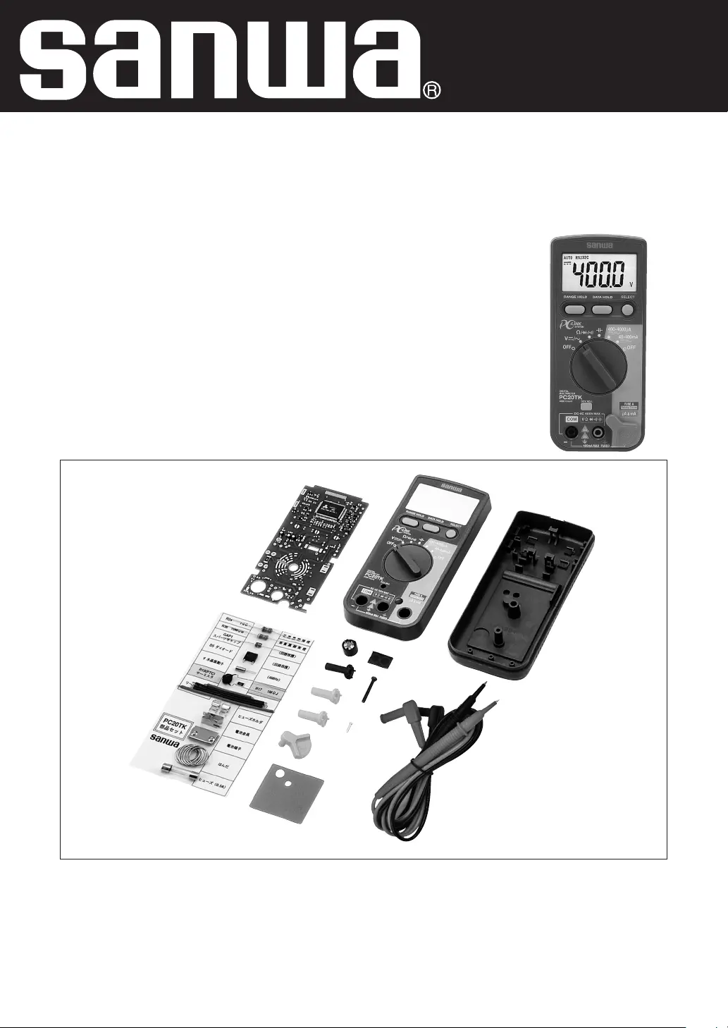
MULTIMETER
PC20TK
Assembling Training for
Digital Multimeter
Instruction Manual for Assembling and Operation Procedures
Produktspecifikationer
| Varumärke: | Sanwa |
| Kategori: | Inte kategoriserad |
| Modell: | PC20TK |
Behöver du hjälp?
Om du behöver hjälp med Sanwa PC20TK ställ en fråga nedan och andra användare kommer att svara dig
Inte kategoriserad Sanwa Manualer

18 September 2024
Inte kategoriserad Manualer
Nyaste Inte kategoriserad Manualer
9 April 2025
9 April 2025
9 April 2025
9 April 2025
9 April 2025
9 April 2025
9 April 2025
9 April 2025
9 April 2025
9 April 2025