StarTech.com PEX8S1050LP Bruksanvisning
StarTech.com Inte kategoriserad PEX8S1050LP
Läs gratis den bruksanvisning för StarTech.com PEX8S1050LP (2 sidor) i kategorin Inte kategoriserad. Guiden har ansetts hjälpsam av 14 personer och har ett genomsnittsbetyg på 4.2 stjärnor baserat på 4 recensioner. Har du en fråga om StarTech.com PEX8S1050LP eller vill du ställa frågor till andra användare av produkten? Ställ en fråga
Sida 1/2
Quick-Start Guide
To view manuals, FAQs, videos, drivers, downloads, technical drawings, and more, visit www.startech.com/support.
Manual Revision: December 17, 2019 12:04 PM
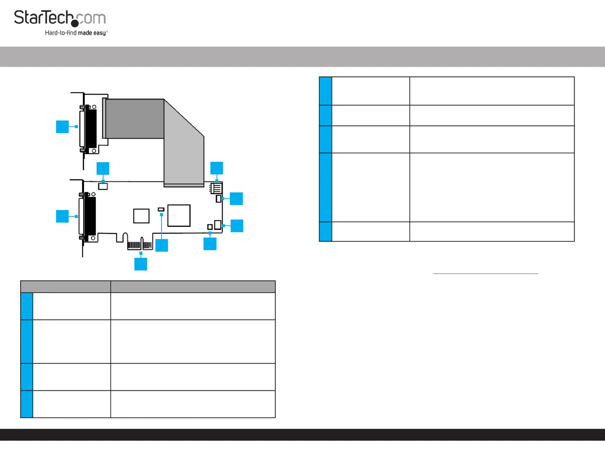
Product Diagram (PEX8S1050LP)
ComponentFunction
1
S5 - S8: DB44 Pin
Connector to 4-Port
Breakout Cable
• Used to connect the DB44 to 4-Port DB9
Breakout Cable.
2
JP 5 - Power Over
Serial Connector
• Used to set pin 9 on the DB9 connector (S1 -
S4) to RI (no power) or to DC power. The JP2
Aux Power Source Selector determines the
voltage 12 or 5.
• Default position is RI.
3
S1 - S4: DB44 Pin
Connector to 4-Port
Breakout Cable
• Used to connect the DB44 to 4-Port DB9
Breakout Cable.
4PCI Express Connector
• Used to connect the to PCI Express Card
the PCI Express expansion slot on the Host
Computer.
8-Port PCI Express Low Prole RS232 Serial Card | 16C1050 UART
5JP1: PME
• Used to enable or disable the wake from sleep
setting.
• Default position is disable.
6JP4: Mode
• Used for factory testing.
• For normal use the jumper must be set to CEN.
7
JP6: S5 - S8
Power Over Serial
Connectors
• Used to enable or disable power over serial for
S5 - S8 connectors.
8
JP2: AUX Power
Source Selector
• Used to select the DC power source for Pin 9 on
the DB9 connector.
• Power supplied by Internal 12V:
motherboard’s PCI Express Slot.
• Power supplied by J3 Power External 12V:
Connector.
• Power supplied by J3 Power External 5V:
Connector.
9
J3 Aux. Power
Connector
• Used to connect an external power source to
the .Serial Card
Requirements
For the latest requirements, please visit www.startech.com/PEX8S1050LP
Installation
WARNING! PCI Express cards can be severely damaged by static electricity. Be sure
that you are properly grounded before touching the .Serial Card
1. Turn O the Host Computer.
2. Remove the chassis cover from the .Host Computer
3. Locate a , using a (sold separately) remove the PCI Express SlotScrewdriver Screw
used to secure the and set the aside. PCI Express Slot CoverScrew
4. Align the on the with a . While PCI Express ConnectorSerial CardPCI Express Slot
applying pressure evenly across the top edge of the , insert the Serial CardSerial
Card PCI Express SlotSerial Cardinto the , ensuring that the is properly aligned
with the rear panel slot.
5. Using a and the removed in step 3, secure the to ScrewdriverScrewSerial Card
the motherboard and rear chassis. Secure the additional serial port provided by the
daughter board (smaller circuit board) to an adjacent rear bracket.
6
2
5
1
3
7
8
9
4
Produktspecifikationer
| Varumärke: | StarTech.com |
| Kategori: | Inte kategoriserad |
| Modell: | PEX8S1050LP |
Behöver du hjälp?
Om du behöver hjälp med StarTech.com PEX8S1050LP ställ en fråga nedan och andra användare kommer att svara dig
Inte kategoriserad StarTech.com Manualer

18 Mars 2025
18 Mars 2025
3 Januari 2025
2 Januari 2025
2 Januari 2025
2 Januari 2025
2 Januari 2025
2 Januari 2025
2 Januari 2025
2 Januari 2025
Inte kategoriserad Manualer
Nyaste Inte kategoriserad Manualer
9 April 2025
9 April 2025
9 April 2025
9 April 2025
9 April 2025
9 April 2025
9 April 2025
9 April 2025
9 April 2025
9 April 2025