Supermicro SuperServer 2029P-C1R Bruksanvisning
Supermicro Server SuperServer 2029P-C1R
Läs gratis den bruksanvisning för Supermicro SuperServer 2029P-C1R (1 sidor) i kategorin Server. Guiden har ansetts hjälpsam av 17 personer och har ett genomsnittsbetyg på 4.4 stjärnor baserat på 9 recensioner. Har du en fråga om Supermicro SuperServer 2029P-C1R eller vill du ställa frågor till andra användare av produkten? Ställ en fråga
Sida 1/1
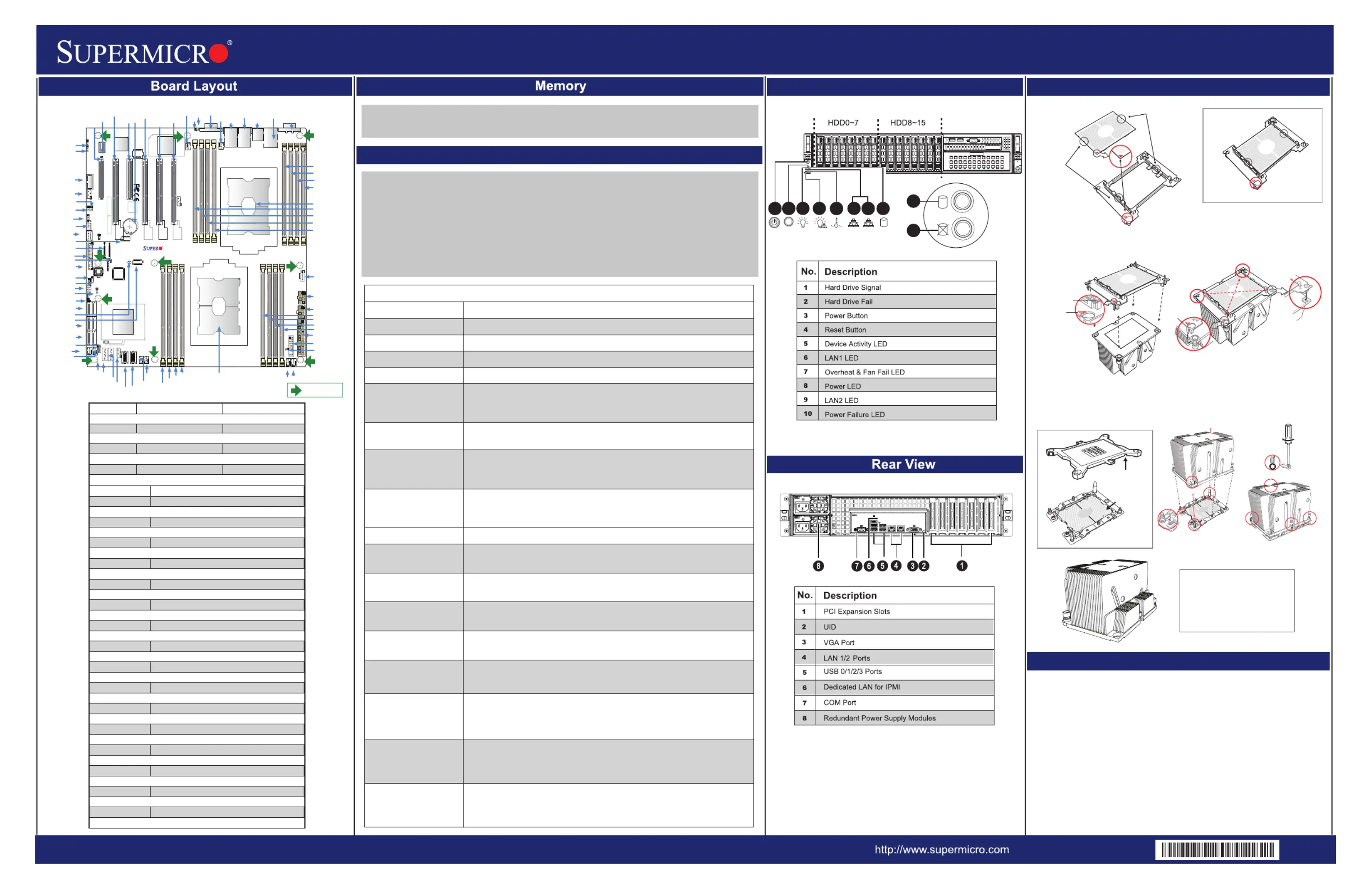
SuperServer 2029P-C1R/C1RT Quick Reference Guide
JumpeDescriptioDefaultSettinrn g
)lamroN( nepOraelC SOMC1TBJ
)delbanE( 2-1 sniPelbanE oiduA1GPJ
JPLLAN1/LAN2EnablPins1-2(Enabled1 e )
)lamroN( 2-1 sniPyrevoceR EM1EMPJ
JPMEManufacturingModeSelecPins1-2(Normal2 t )
JVRM1/JVRMVRMSMBClock(toBMCorPCHPins1-2(BMC,Normal 2 ) )
JWDatchDogimerEnablPins1-2(ResettoSystem1W T e )
ConnectoDescriptiorn
tekcos yrettab SOMC draobnO1TB
COM1/COMBackpanelCOMport/COMheaderforfrontacces2 s
F FFAN1-6,ANA/ANSystemcoolingfanheadersAN1-B (FFAN6,ANA,AN F F B)
IPMI_LANDedicatedIPMI_LANpor t
I-SA0~3,I-SA4~3.0connectionheadersupportedbytheIntelPCAT AT7SA AT H
redaeh DEL rewoP1DJ
redaeh lortnoC lenaP tnorF1FJ
JHFI1/JHFIHostFabricInterface(HFI)sidebandheadersfortheHFIcard2 s
JIPMB4-pinBMCExternal1 I
2
C )header(foranIPMI-supportedcard
redaeh noisurtnI sissahC1LJ
JM2_M.2slo1 t
JNVI
2
C1 INVMe
2
C rheade
JNVME1/JNVMENVMeSlot1/NVMeSlot2 2
JPI
2
C1 IPowerSupplySMBbus
2
C rheade
JPWR1/JPWR8-pinPowerSupplyconnector2 s
JPWR24-pin3 ATXmainpowersupplyconnecto r
JRKRAIDKeyforonboarddevice1 SA ATs
JSTBYStandbypowerheade1 r
JTPMrustedPlatformModule(TPM)/Port80connecto1T r
LAN1/LAN2(NoteGigabitLAN/10GLANEthernetportsonthebackpane ) l
S-SA0-S-S3.0connectionHeadersupportedbytheIntelSCUAT3ATA
S-SA4/S-SPoweredS-SATATA5
ATA sPortsSuperDOM(DiskOnModule)device
SLOT1/SLOTPCI-Express3.0X8Slotssupportedby3 1CPU
SLOTPCI-Express3.0X16SlotsupportedbyCPU2 1
SLOT4/SLOT5/SLOTPCI-Express3.0X16SlotssupportedbyCPU6 2
T3 t-SGPIOGeneralPurposeSerialI/Opor
itnedI tinUDIUfier(UID)switc h
USB0/1USB4/BackpanelUSB2.0ports(USB0/1)USB3.0ports(USB4/5 & 5 & )
USB2/FrontAccessibleUSB2.0headerforUSB2/3 3
USBype6T A rUSB3.0Heade
USB7/FrontAccessibleUSB3.0headerforUSB7/88
VGVGPorAA t
CPU1
BIOS
LICENSE
MAC CODEBAR CODE
JTPM1
JPCIE3
JPCIE1
JPCIE6
JPCIE4
JPCIE2
JPCIE5
JRK1
JPWR3
JPI2C1JPWR2JPWR1
JF1
JL1
JSTBY1
BT1
T-SGPIO3
JWD1
JPME2
JPL1JIPMB1
LE1
LEDM1
JBT1
FAN4
FAN3
FAN1FAN2
FAN5
FANA
FANB
VGA
JHFI1
LE2
P1-DIMMA2
P1-DIMMA1
P1-DIMMB1
P1-DIMMC1
P1-DIMMF1
P1-DIMME1
P1-DIMMD1
P1-DIMMD2
P2-DIMMB1
P2-DIMMA1
P2-DIMMA2
P2-DIMMD2
P2-DIMMD1
P2-DIMME1
P2-DIMMF1
BMC
LAN CTRL
FAN6
BIOS
JVRM1
JVRM2
JM2_1
LE3
A
JPME1
JD1
M.2-PCH
A
C
JPG1
JNVI2C2
S-SA5AT
S-SA4AT
(3.0)USB7/8
(3.0)
USB 6
USB 2/3
COM2
CPU1 SLOT1 PCI-E 3.0 X8
CPU1 SLOT2 PCI-E 3.0 X16
CPU1 SLOT3 PCI-E 3.0 X8
CPU2 SLOT4 PCI-E 3.0 X16
CPU2 SLOT5 PCI-E 3.0 X16
CPU2 SLOT6 PCI-E 3.0 X16
UID
LAN2LAN1
USB0/1
(2.0)
USB4/5 (3.0)
IPMI_LAN
COM1
S-SA 0~3AT
I-SATA 4~7
I-SA 0~3AT
CPU2
(2.0)
Rev. 1.21
PCH
P2-DIMMC1
X11DPi-N(T)
JNVME1
JNVME2
JNVI2C1
JHFI2
USB2/3
JWD1
T-SGPIO3
SLOT4
SLOT6
SLOT5
SLOT3
SLOT2
SLOT1
LEDM1
JPL1
COM2
JIPMB1
JVRM1
JVRM2
JPME2
USB6
USB7/8
JM2_1
JTPM1
JPME1
JD1
JRK1
LE3
S-SA0-AT3
I-SA0-AT3
I-SA4-AT7
FANB
FANA
JL1
BT1
FAN6
LE1
UID
VGA
FAN5
LAN2
LAN1
USB0/1
IPMILA N
USB4/5
COM1
JPI2C1
JPWR1
JPWR2
JPWR3
JF1
LE2
P2-DIMMD2
P2-DIMMD1
P2-DIMME1
P2-DIMMF1
P1-DIMMA2
P1-DIMMA1
P1-DIMMB1
P1-DIMMC1
P2-DIMMC1
P2-DIMMB1
P2-DIMMA1
P2-DIMMA2
FAN3
FAN4
JSTBY1
S-SATA4
S-SATA5
JNVI2C1
JNVME1
JNVME2
P1-DIMMD2
P1-DIMMD1
P1-DIMME1
P1-DIMMF1
JBT1
FAN1
FAN2
CPU1
CPU2
JPG1
= mounting hole
JHFI2
JHFI1
JBT1
MNL-1993-QRG
Rev. 1.0b
1
RESET
3
4
7
6
5
8
2
910
1
2
Front View & Interface
Memory Support
This system supports dual Intel Xeon Scalable-SP or 2nd Gen Intel Xeon Scalable-SP
series processors with support of UltraPath Interconnect (UPI) of up to 10.4 GT/s.
This system supports up to 4TB of 3DS LRDIMM, LRDIMM, 3DS RDIMM, RDIMM, NV-DIMM
DDR4 (288-pin) ECC 2933/2666/2400/2133 MHz memory modules in 16 slots.
Notes:
1. Up to 5TB is supported with (L)RDIMM and DCPMM populated in a balanced memory
configuration.
2. 2933 MHz memory is supported by 2nd Gen Intel Xeon Scalable-SP(82xx/62xx) series
processors only.
3. Unbalanced memory configuration decreases memory performance and is not recommended.
When 1 CPU is used:Memory Population Sequence
1 CPU & 1 DIMMCPU1: P1-DIMMA1
1 CPU & 2 DIMMsCPU1: P1-DIMMA1/P1-DIMMD1
1 CPU & 3 DIMMs CPU1: P1-DIMMC1/P1-DIMMB1/P1-DIMMA1
1 CPU & 4 DIMMsCPU1: P1-DIMMB1/P1-DIMMA1/P1-DIMMD1/P1-DIMME1
1 CPU & 5 DIMMs
(Unbalanced: not
recommended)
CPU1: P1-DIMMC1/P1-DIMMB1/P1-DIMMA1/P1-DIMMD1/P1-DIMME1
1 CPU & 6 DIMM
CPU1: P1-DIMMC1/P1-DIMMB1/P1-DIMMA1/P1-DIMMD1/P1-DIMME1/
P1-DIMMF1
1 CPU & 7 DIMMs
(Unbalanced: not
recommended)
CPU1:P1-DIMMC1/P1-DIMMB1/P1-DIMMA1/P1-DIMMA2/P1-DIMMD1/
P1-DIMME1/P1-DIMMF1
1 CPU & 8 DIMMs
(Unbalanced: not
recommended)
CPU1: P1-DIMMC1/P1-DIMMB1/P1-DIMMA1/P1-DIMMA2/P1-DIMMD2/
P1-DIMMD1/P1-DIMME1/P1-DIMMF1
When 2 CPUs are used:Memory Population Sequence
2 CPUs & 2 DIMMs
CPU1: P1-DIMMA1
CPU2: P2-DIMMA1
2 CPUs & 4 DIMMs
CPU1: P1-DIMMA1/P1-DIMMD1
CPU2: P2-DIMMA1/P2-DIMMD1
2 CPUs & 6 DIMMs
CPU1: P1-DIMMC1/P1-DIMMB1/P1-DIMMA1
CPU2: P2-DIMMC1/P2-DIMMB1/P2-DIMMA1
2 CPUs & 8 DIMMs
CPU1: P1-DIMMB1/P1-DIMMA1/P1-DIMMD1/P1-DIMME1
CPU2: P2-DIMMB1/P2-DIMMA1/P2-DIMMD1/P2-DIMME1
2 CPUs & 10 DIMMs
CPU1: P1-DIMMC1/P1-DIMMB1/P1-DIMMA1/P1-DIMMD1/P1-DIMME1/
P1-DIMMF1
CPU2: P2-DIMMB1/P2-DIMMA1/P2-DIMMD1/P2-DIMME1
2 CPUs & 12 DIMMs
CPU1: P1-DIMMC1/P1-DIMMB1/P1-DIMMA1/P1-DIMMD1/P1-DIMME1/
P1-DIMMF1
CPU2: P2-DIMMC1/P2-DIMMB1/P2-DIMMA1/P2-DIMMD1/P2-DIMME1/
P2-DIMMF1
2 CPUs & 14 DIMMs
(Unbalanced: not
recommended)
CPU1: P1-DIMMC1/P1-DIMMB1/P1-DIMMA1/P1-DIMMA2/P1-DIMMD1/
P1-DIMME1/P1-DIMMF1
CPU2: P2-DIMMC1/P2-DIMMB1/P2-DIMMA1/P2-DIMMA2/P2-DIMMD1/
P2-DIMME1/P2-DIMMF1
2 CPUs & 16 DIMMs
(Unbalanced: not
recommended)
CPU1: P1-DIMMC1/P1-DIMMB1/P1-DIMMA1/P1-DIMMA2/P1-DIMMD2/
P1-DIMMD1/P1-DIMME1/P1-DIMMF1
CPU2: P2-DIMMC1/P2-DIMMB1/P2-DIMMA1/P2-DIMMA2/P2-DIMMD2/
P2-DIMMD1/P2-DIMME1/P2-DIMMF1
Memory Population Table
CPU Installation
Caution
On Locations of (C, D), the notches
snap onto the heat sink’s
mounting holes
CPU and Processor Clip
Attaching the Processor Carrier Assembly to the Heatsink to Form the Processor Heatsink
Module (PHM)
Dust Cover
CPU Socket
Removing the Dust Cover from
the CPU Socket
Installing the Processor Heatsink Module (PHM)
Remove the dust cover from the CPU socket, exposing the
socket and socket pins as shown on the illustration below.
No: te
Do not touch the socket pins to avoid damaging
them, causing the CPU to malfunction.
Note:Do not use excessive force when tightening the screws to avoid
damaging the LGA lands and the processor.
CPU (Upside Down)
w/CPU LGA Lands up
Align Notch C of the
CPU and Notch C of
the Processor Clip
Processor Carrier Assembly (with CPU mounted
on the Processor Clip)
A
B
C
Allow carrier to
latch onto CPU
Allow carrier to
latch onto CPU
Processor Carrier Assembly
On Locations (A, B), the notches
snap onto the heatsink’s sides
Make sure Mounting
Notches snap into place
A
B
D
C
Printed TriangleSmall Guiding Post
Mounting the Processor Heatsink Module
into the CPU socket (on the motherboard)
Heatsink
(Upside Down)
Triangle on the CPU
Triangle on the
Processor Carrier
Oval D
Oval C (Large Guiding Post)
1
2
3
4
CPU/Heatsink Package
(Upside Down)
Align Notch B of the
CPU and Notch B of
the Processor Clip
Tighten the screws in the
sequence of 1, 2, 3, 4 (top 3 quarter view)
B
C
B
C
Pin 1
A
A
Align CPU Pin 1
a
b
A
B
d
c
D
C
Socket Pins
Remove the plastic protective
cover from the CPU socket.
Do not touch or bend
the socket pins.
T30 Torx Driver
Use a torque of
12lbf-in
SAFETY INFORMATION
IMPORTANT: See installation instructions and safety warning before connecting
system to power supply.
http://www.supermicro.com/about/policies/safety_information.cfm
WARNING:
To reduce risk of electric shock/damage to equipment, disconnect power from
server by disconnecting all power cords from electrical outlets.
If any CPU socket empty, install protective plastic CPU cap
WARNING:
Always be sure all power supplies for this system have the same power output.
If mixed power supplies are installed, the system will not operate.
For more information go to : http://www.supermicro.com/support
!
!
!
Note:
a) SNK-P0068PSC is for CPU 1 and
SNK-P0068PS is for CPU 2
b) The cut-off section of SNK-P0068PSC
must face towards power supply
SNK-P0068PSC
Produktspecifikationer
| Varumärke: | Supermicro |
| Kategori: | Server |
| Modell: | SuperServer 2029P-C1R |
Behöver du hjälp?
Om du behöver hjälp med Supermicro SuperServer 2029P-C1R ställ en fråga nedan och andra användare kommer att svara dig
Server Supermicro Manualer

16 Februari 2026
31 Januari 2026
31 Januari 2026
30 Januari 2026
26 Januari 2026
13 September 2025
13 September 2025
12 September 2025
12 September 2025
12 September 2025
Server Manualer
Nyaste Server Manualer
1 April 2026
24 Mars 2026
19 Mars 2026
3 Februari 2026
20 Oktober 2025
19 Oktober 2025
19 Oktober 2025
19 Oktober 2025
19 Oktober 2025
19 Oktober 2025