Tektronix P6616 Bruksanvisning
Tektronix Inte kategoriserad P6616
Läs gratis den bruksanvisning för Tektronix P6616 (8 sidor) i kategorin Inte kategoriserad. Guiden har ansetts hjälpsam av 32 personer och har ett genomsnittsbetyg på 4.6 stjärnor baserat på 8 recensioner. Har du en fråga om Tektronix P6616 eller vill du ställa frågor till andra användare av produkten? Ställ en fråga
Sida 1/8
xx
ProductDescription
TheP6616general-purposelogicprobeconnectstheTektronix
MSO/DPO5000SeriesandMSO4000BSeriesofmixed-signal
oscilloscopestodigitalbusesandsignalsonyourtargetsystem.
Theprobecontains16datachannelssplitbetweentwoleadsets
(GROUP1andGROUP2).
Allleadsincludeagroundconnectionatthetip.Youcan
connecttheprobeleadsseparatelytothetargetsystem,orgroup
theleadstogetherusingtheprobetipholders.
ConnectingtheProbetotheOscilloscope
Connecttheprobeasshownintheillustrationbelow.
1.Inserttheprobelabel-sideupintotheconnectoronthe
oscilloscope.
2.Toremovetheprobe,squeezethebuttonsonthesideand
pullouttheprobe.
ConnectingtheProbetoYourCircuit
Attachtheprobetothecircuitusingtheconnectorsandadapters
shownonthebackoftheseinstructions.Selectthebestmethod
foryourneeds,andthenproceedtoSettinguptheProbe.
SettingUptheProbe
Tosetandviewthedigitalchannelparameters,dothe
following:
OnMSO/DPO5000Seriesinstruments,select
Vertical>DigitalSetup.
OnMSO/DPO4000BSeriesinstruments,pushtheD15–D0
button.
Theparameterslistedbelowcanbesetoneachdigitalchannel:
Thresholdvoltageandverticalposition(thedefault
thresholdsettingis1.4V)
Signalheightandposition(setonceforall16channels)
Channellabel
Tosetandviewbuscharacteristics,dothefollowing:
OnMSO/DPO5000Seriesinstruments,usethecontrolsin
theBusSetupscreen.
OnMSO/DPO4000BSeriesinstruments,pushtheB1to
B4buttons.
Thesetupscreensallowyoutosetandviewbuscharacteristics
suchas:
Clocktype
Bustype(SerialorParallel)
Buswidth
Displayformat(Hex,Binary,orASCIIsymbols)
Parallelbussetupinformationisresidentonsomeoscilloscope
models.However,forotherbusessuchasSPIandI2C,you
musthavetheappropriateoption.Seeyouroscilloscopemanual
orproductdatasheetfornomenclatureandorderingdetails.
FunctionalCheck
Logicactivityimmediatelydisplaysonallconnected,active
channels.Ifyoudonotseeanactivesignal:
1.PushtheTriggerbutton.
2.SelectEdgefortriggertype.
3.Selectthechannelthatyouaresettingupasthesource.
4.OnMSO/DPO4000BSeriesinstruments,pushtheAutoset
button.
Ifyoudonotseeanactivesignal,tryanotherprobechannel(or
analogprobe)toverifycircuitactivityatthetestpoint.
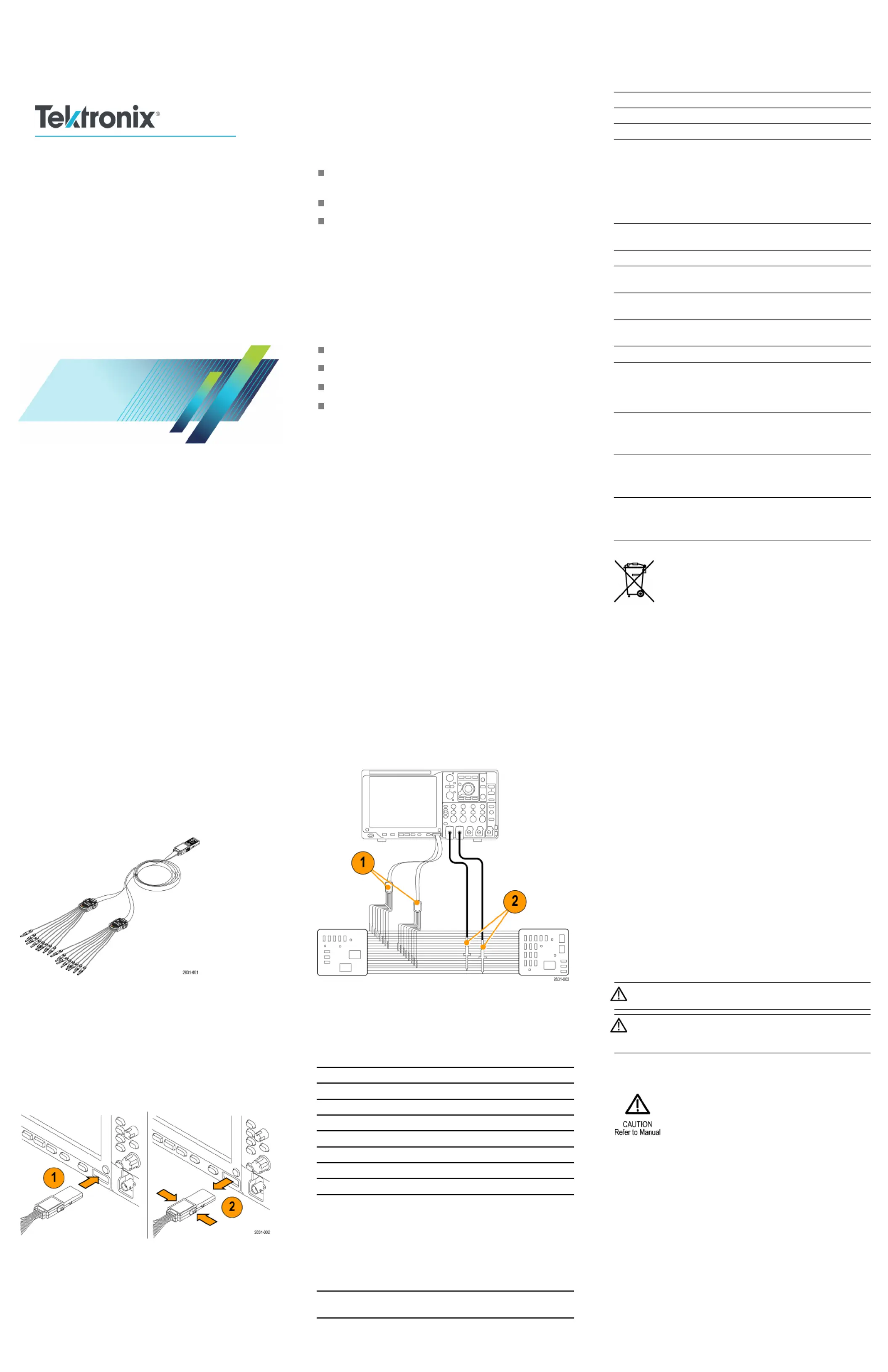
TypicalApplication
1.UsetheP6616probetoviewdigitalsignalsonasystem
bus.
2.Useananalogprobe,suchastheTPP0500orTPP1000
activeprobetoviewanalogwaveforminformation.
Accessories
Thefollowingstandardaccessoriesshipwiththeprobeandare
shownintheillustrationonthefollowingpage.
ItemDescriptionQuantityPartnumber
—LogicprobeaccessorykitItem1–6020-2662-XX
1Extensiongroundtip
1setof20
020-2711-XX
2Probetip
1setof10
131-5638-11
3
ICgrabber1setof20
020-2733-XX
4Probetipholder2ea352-1115-XX
5
8”Groundlead1setof2
020-2713-XX
6
3”Groundlead1setof8
020-2712-XX
Instructions
1
1ea071-2831-XX
1
Instructionsareincludedwiththeprobe,butn
otintheaccessorykit.
Theinstructionscanbedownloadedatwww.tektronix.com/manuals.
Theseoptionalaccessoriescanbeorderedforyourprobe:
DescriptionPartnumber
P6960ProbeD-MAXFootprintto
SquarePinHeaderAdapter
NEX-P6960PIN
Specifications
Table1:Electricalandmechanicalspecifications
CharacteristicDescription
Inputchannels16digital
Inputresistance
100kΩ±1.0%
Inputcapac
itance
3.0pF
Inputsignalswing
Minimum400mVp-p
Maximum
30Vp-p,≤200MHz(centeredaround
theDCthresholdvoltage)attheprobetip
10Vp-p,≥200MHz(centeredaround
theDCthresholdvoltage)attheprobetip
Maximumnondest–
ructiveinputsignal
30Vp-p,42Vpeak,±50VDC
Thresholdvoltage±40V
Minimumdetectable
pulsewidth
1ns
Maximuminput
togglerate
500MHz
Digitalchannel-to-
digitalchannelskew
200ps
Probelength
1.0m(3.28ft)
Table2:Environmentalspecifications
CharacteristicDescription
Temperature
Operating
Nonoperating
0°Cto+50°C(+32°Fto+122°F)
–55°Cto+75°C(–67°Fto+167°F)
Humidity
Operating
Nonoperating
5%to95%relativehumidity
10%to95%relativehumidity
Altitude
Operating
Nonop
erating
4.6km(15,092ft)maximum
15km(
50,000ft)maximum
EquipmentRecycling.Thisproductcomplies
withtheEuropeanUnion’srequirementsaccording
toDire
ctive2002/96/EConwasteelectrical
andelectronicequipment(WEEE).Formore
informationaboutrecyclingoptions,checkthe
Support/ServicesectionoftheTektronixWebsite
(www.tektronix.com).
SafetySummary
ConnectandDisconnectProperly.Connecttheprobeoutput
tothemeasurementinstrumentbeforeconnectingtheprobe
tothecircuitundertest.Disconnecttheprobeinputandthe
probegroundfromthecircuitundertestbeforedisconnecting
theprobefromthemeasurementinstrument.
ObserveAllTerminalRatings.Toavoidfireorshockhazard,
observeallratingsandmarkingsontheproduct.Consultthe
productmanualforfurtherratingsinformationbeforemaking
connectionstotheproduct.
DonotOperateWithoutCovers.Donottouchexposed
connectionsandcomponentswhenpowerispresent.
AvoidExposedCircuitry.Donottouchexposedconnections
andcomponentswhenpowerispresent.
DoNotOperateWithSuspectedFailures.Ifyoususpectthereis
damagetothisproduct,haveitinspectedbyqualifiedservice
personnel.
DoNotOperateinWet/DampConditions.DoNotOperateinan
ExplosiveAtmosphere.
KeepProductSurfacesCleanandDry.
SafetyTermsandSymbolsinThisManual.
Thesetermsmayappearinthismanual:
WARNING.Warningstatementsidentifyconditionsor
practicesthatcouldresultininjuryorlossoflife.
CAUTION.Cautionstatementsidentifyconditionsor
practicesthatcouldresultindamagetothisproductor
otherproperty.
SymbolsontheProduct.Thissymbolmayappearonthe
product:
ContactingTektronix
Website:www.tektronix.com
Phone:1-800-833-9200
Address:Tektronix,Inc.
Departmentorname(ifknown)
14200SWKarlBraun
DriveP.O.Box500
Beaverton,OR97077
US
A
Email:
techsuppor[email protected]
WarrantyInformation
Forwarrantyinformation,gotowww.tektronix.com/warranty.
P6616
General-PurposeLogicProbe
Instruct
ions
x
1
*P0712
83101*
071-2831-01
Produktspecifikationer
| Varumärke: | Tektronix |
| Kategori: | Inte kategoriserad |
| Modell: | P6616 |
Behöver du hjälp?
Om du behöver hjälp med Tektronix P6616 ställ en fråga nedan och andra användare kommer att svara dig
Inte kategoriserad Tektronix Manualer

24 September 2024
24 September 2024
Inte kategoriserad Manualer
Nyaste Inte kategoriserad Manualer
9 April 2025
9 April 2025
9 April 2025
9 April 2025
9 April 2025
9 April 2025
9 April 2025
9 April 2025
9 April 2025
9 April 2025