Uni-T UT209A Bruksanvisning
Uni-T Multimeter UT209A
Läs gratis den bruksanvisning för Uni-T UT209A (2 sidor) i kategorin Multimeter. Guiden har ansetts hjälpsam av 18 personer och har ett genomsnittsbetyg på 4.5 stjärnor baserat på 2 recensioner. Har du en fråga om Uni-T UT209A eller vill du ställa frågor till andra användare av produkten? Ställ en fråga
Sida 1/2
Overview
This Operating Manual covers information on safety and cautions. Please read
the relevant information carefully and observe all the Warnings and Notes strictly.
Warning
To avoid electric shock or personal injury, read the “Safety Information”
carefully before using the Meter.
The Meter can measure AC/DC Voltage, AC/DC Current, Frequency, Duty Cycle,
Resistance, Diodes, Continuity and etc.
UT208A has extra temperature and Capacitance features.
Unpacking Inspection
Open the package case and take out the Meter. Check the following items
carefully for any missingordamagedpart:
Item Description Qty
1 English Operating Manual 1 pc
2 Test Lead 1 pair
3 Point Contact Temperature Probe (Only UT208A) (This
included point contact temperature probe canonly be used
up to 230℃. For any measurement is higher than that, the
rod type temperature probe must be used)
4 Toolbox
1 pc
5
9V Battery (NEDA1604A or 6LF22) 1 pc
In the event youfindanymissingordamaged part,pleasecontact yourdealer
immediately.
1 pair
Safety Information
This Meter complies with IEC61010, Pollution Degree 2, Overvoltage Category
(CAT.Ⅱ600V, CAT Ⅲ300V) and Double Insulation standards.
CAT II: Local level, appliance, PORTABLE EQUIPMENT etc., with smaller
transient overvoltages than CAT III.
CAT III: Distributionlevel, fixedinstallation, with smaller transient overvoltages than CAT IV.
Use theMeteronlyasspecifiedin thisoperatingmanual, otherwise theprotection
providedby theMetermay beimpaired.
In this manual, a Warning identifies conditions and actions that pose hazards to
the user, or may damage the Meter or the equipment under test.
A Note identifies the information that user should pay attention to.
Warning
To avoid possible electric shock or personal injury, and to avoid possible damage
to the Meter or to the equipment under test, adhere to the following rules:
● Before using theMeter inspect the case. Do not use theMeter if it is
damagedor the
case (or part of the case) is removed. Look for cracks or
missingplastic. Pay attention to theinsulation around the connectors.
● Inspect the test leads fordamaged insulation or exposed metal. Check
the test leads for continuity. Replace damaged test leadswith identical
modelnumber or electrical specifications before using theMeter.
● Donot apply more than therated voltage, as marked on theMeter, between
the terminals orbetween any terminal and grounding. If the value to be
measuredis unknown, use themaximum measurement position and reduce
therange step by step until a satisfactory reading is obtained.
● Whenmeasurement has been completed, disconnect the connection
between the test leads and the circuit under test, remove the testing leads
away from theinput terminals of the Meter and turn theMeter power off.
● The rotary switch should be placed in theright position and no any
changeover of range shallbe made during measurement to prevent damage
of the Meter.
● Donot carry out the measurement when theMeter’s back case and battery
compartment are not closed to avoid electric shock.
● Donot input higher than1000V in DC or 750 V in AC between the two
Meter’s input terminal to avoid electric shock and damages to theMeter.
● When theMeter is working at an effective voltage over 70V in DC or 33V rms
inAC, special care should be taken for there is danger of electric shock.
● Use theproper terminals, function, and range foryour measurement
s.
● Donot use or store theMeter in an environment of high temperature,
humidity, explosive, inflammableand strong magnetic field. The performance
of the Meter may deteriorate after dampened.
● Whenusing the test leads, keepyour fingers behind thefinger guards.
● To avoid electric shock, do not touch the bare wires, connectors, unused
input terminalsor the circuit under testing during measurement.
● Disconnect circuit powerand discharge all high-voltage capacitors before
testing resistance, continuity and diode.
● Replace thebattery as soon as thebattery indicator appears. With a low
battery, theMeter might produce false readings that canlead to electric
shockand personal injury.
● Whenservicing theMeter, use only the replacement parts with the same
model or identical electrical specifications.
● The internal circuit of the Meter shall not be altered at will to avoid damage
of the Meter and any accident.
● Soft cloth and mild detergent should be used to clean the surface of the
Meter when servicing. No abrasive and solvent shouldbe used to prevent
the surface of the Meter from corrosion, damage and accident.
● The Meter is suitable forindoor use.
● Turn theMeter off when it is not in use and takeout the battery when not
using for a long time.
● Constantly check thebattery as it may leak when it has been using forsome
time, replace thebattery as soonas leaking appears. A leaking battery will
damage theMeter.
International Electrical Symbols
Double Insulated
Grounding
Warning. Refer to the Operating Manual
AC (Alternating Current)
DC(Direct Current)
Continuity Test
Diode
Low Battery Indication
AC or DC
Danger of High Voltage
Conforms to Standards of European Union
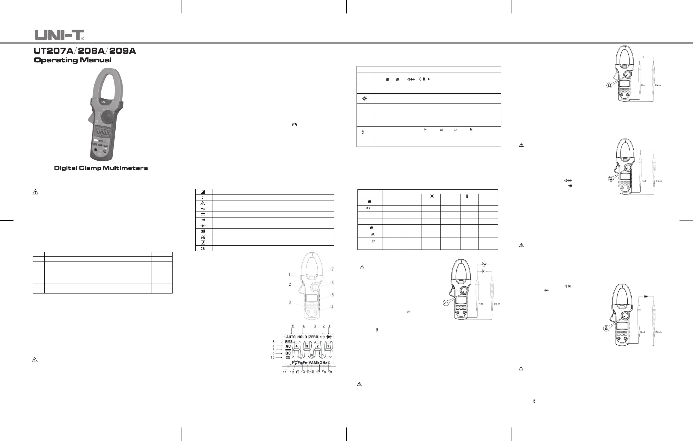
The Meter Structure
(See Figure 1)
①Hand Guards: to protect user’s hand from
touching thedangerous area.
②Lever: press the lever to open the
transformerjaws. When the lever is
released, the jaws will close.
③ Functional Buttons
④ Input Terminals
⑤LCDDisplay
⑥Rotary Switch
⑦ Transformer Jaw: designed to pick up the AC
andDC current flowing through the conductor.
It could transfer current to voltage. The tested
Figure 1
Display Symbols
(See Figure 2)
Figure 2
1. Test of diode
2. The continuity buzzer is on
3. Indicator for zeroing
4. Data hold is active
5. The Meter is in the auto range mode in
which the Meter automatically selects
therange with thebest resolution.
6. True RMS indicator
7. Indicator for AC voltage or current
8. Indicates negative reading
9. Indicator for DC voltage
10. Thebattery is low.
Warning: To avoid false readings, which could lead to possible electric shock
orpersonal injury, replace thebattery as soon as the battery indicator appears.
11. The unit of transistor hEF
12. Theunit of temperature, ℃: Centigrade temperature
13. Theunit of temperature, ℉: Fahrenheit temperature
14. Theunit of capacitance (UT208A only)
15. Volts.The unit of voltage. mV: Millivol
t.
16. Amperes(amps). Theunit of current.
17. Theunit of resistance. (Ω: Ohm, kΩ:Kilohm, MΩ:Megohm )
conductormust vertically go through the Jaw center.
18. Theunit of frequency. (Hz: Hertz, KHz: Kilohertz, MHz: Meghertz)
19. Duty cyclemeasurement
Functional Buttons
Below table indicated for information about the functional button operations.
SELECT
RANGE
HOLD
Button
Operation Performed
Press SELECT button to select the alternate functions including
V , Aand . ( UT208A only)
Ω
Range feature: Exit AUTO andenterMANUAL ranging. In MANUAL,
select next input range. EXIT to return to AUTO. AUTO is default.
Press once to turn the display backlight on. Press again to turn the
display backlight off, otherwiseit willautomatically off after 15 seconds.
● Press HOLD to enter theHold mode in any mode (except
%Hz), theMeter beeps.
● Press HOLD again to exit the Hold mode to return to
measurement mode, the Meter beeps.
● Turn therotaryswitchorpressanybuttoncanalsoexit hold mode.
ZERO
When the Meter is at %Hz, V and A , press%Hz to
measure frequency andduty cycle.
Press ZERO to zeroing the display before measuring AC/DC
voltage, AC/DC current, resistance and capacitance.
Hz%
Automatic Power Off
The display blanks and the Meter goes into a “sleep” mode if you have not
changed therotary switch positionorpressed a button for15minutes. While
in Sleepmode, pressing theany effective Functionalbuttonor turning the
rotaryswitch could turn theMeteron. To disable the sleep mode function, press
SELECT buttonwhile turningon themeter.
The Effectiveness of Functional Buttons
Not every functionalbuttons canbeusedonevery rotary switch positions. Below
table describe which functional buttons can be used on which rotary switch positions.
V
Ω
%Hz
40A
400A
1000A
℃
Rotary Switch Functional Buttons
Positions SELECT RANGE HOLD ZERO
%Hz
●
●
N/A
N/A
●
●
●
N/A
●
N/A
●
N/A
N/A
N/A
N/A
N/A
●
●
●
●
●
●
●
●
●
●
●
N/A
●
●
●
●
●
N/A
N/A
●
●
●
●
N/A
●
●
●
N/A
●
●
●
N/A
Measurement Operation
A. Measuring DC/AC Voltage (See Figure 3)
Figure 3
To avoid harm to you or damage to the
Meterfrom eletric shock, do not attempt
to measure voltages higher than 750V AC
or 1000V DC, although readings may be
obtained.
To measure DC/AC voltages, connect the
Meter as follows:
1. Insert the red test leadinto the
andblack test leadinto the COM terminal.
V Hzterminal
2. Set the rotary switch to V . DC mesaurement
mode is a default. Press SELECT to switch to
AC measurement mode. Press RANGE to enter
manual ranging.
3. PressHz% button to measure frequency or duty cycle, but the frequency or
duty cycle readings obtained from this range is only for reference.
4. Connect the test leads across with the object being measured. The measured
valueshows on thedisplay.
Note:
● AC Millivolt is a manual ranging measurement mode.
● In each range, the Meter has an input impedance of 10MΩ.
This loading
effect can cause measurement errors in high impedance circuits. If the
Warning
Ω
circuit impedanceisless thanorequal to 10kΩ, the error is negligible (0.1% or less).
● WhenDC/AC voltage measurement has been completed, disconnect the
connectionbetween the testing leads and the circuit under test and remove
testing leads from theinput terminals.
B. Measuring Resistance(See Figure 4)
Warning
To avoid damage to the Meter or to the devices under test, disconnect circuit
power and discharge all the high-voltage capacitors before measuring resistance.
To measure resistance, connect the Meter as follows:
1. Insert the red test lead into the VΩHz terminal and black test lead into the
COM terminal.
2. Set the rotary switch to Ω
3. Connect the test leads across with the object
beingmeasured. Themeasured valueshows
on thedisplay.
Figure 4
Note:
● To obtain a more precise reading, you could
remove theobjects being tested from the
circuit during measurement.
● The test leadscan add 0.1Ω to 0.3Ω of error
to resistance measurement. To obtain
precisionreadingsinlow-resistance
measurement, short-circuit the input terminals
beforehand, press ZERO to reset to "0" and this
shorted value will be automatically subtracted
from subsequent readings each time you perform
a resistance measurement.
● Forhigh-resistance measurement (>1MΩ), it
isnormal to takeseveral second to obtain a stablereading.
● To avoid harm to you or damages to the Meter from eletric shock, do not
attempt to input voltages higher than33V AC or 70V DC.
● Whenresistance measurement has been completed, disconnec
t the
connectionbetween the testing leads and the circuit under test and remove
testing leads from theinput terminals.
C. Testingfor Continuity(See Figure 5)
Warning
To avoid damage to the Meter or to the
devices under test, disconnect circuit power
and di
scharge all the high-voltage capacitors
before measuring continuity.
To test for continuity, connect theMeter as follows:
1. Insert the red test lead into the
and the black test lead into the COM terminal.
VΩHz terminal
2. Set the rotary switch toand press
SELECTbutton to select
measurement mode.
3. The buzzer sounds if the resistance of a circuit
under test isless than 10Ω.
4. The buzzer may or may not sound if the resistance
of a circuit under test is between 10Ω to 100Ω.
5. The buzzer does not sound if the resistance of a circuit under test is higher
than100Ω.
Figure 5
Note
● To avoid harm to you or damage to the Meter from eletric shock, do not
attempt to input voltages higher than33V AC or 70V DC.
● Whencontinuity testing has been completed, disconnect the connection
between the testing leads and the circuit under test and remove testing leads
from theinput terminals.
D. Testing Diodes(SeeFigure 6)
Warning
To avoid damage to the Meter or to the devices under test, disconnect circuit
power and discharge all the high-voltage capacitors beforetesting diodes.
Use the diode test to check diodes, transistors, and other semiconductor devices.
The diode test sends a current through the semicondutor junction, thenmeasures the
voltagedrop across the junction. Agood silicon junction drops between 0.5V and 0.8V.
To test the diode out of a circuit, connect the Meter as follows:
1. Insert the red test lead into the VΩHz terminal and black test lead into the
COM terminal.
2. Set the rotary switch to . Press SELECT
to switch to measurement mode.
Note
● To obtain a more precise reading, you could
remove theobjects being tested from the
circuit whenmeasuring.
● To avoid harm to you or damage to the
Meter fromeletricshock, donot attempt to
input voltages higher than 33V AC or 70V DC.
● Whendiode testing has been completed,
disconnect theconnectionbetween the testing
leadsand the circuit under test and remove testing leads from the input terminals.
Figure 6
E. Measuring Frequency and Duty Cycle (See Figure 7)
Warning
To avoid harm to you or damage to the Meter from eletric shock, do not
attempt to measure voltages higher than 750V AC or 1000V DC, although
readings may be obtained.
To measure frequency/duty cycle, connect the Meter as follows:
1. Insert the red test lead into the VΩHz terminal and the black test lead into the
COM terminal.
2. Set the rotary switch to %Hz. Frequency measurement mode is a default or
press %Hzbutton to switch to duty cycle measurement mode.
3. Connect the test leads across with the object being measured. The measured
valueshows on thedisplay.
Model UT207A/UT208A/UT209A are 3 3/4 digit AC&DC digital clamp multimeters
(hereinafter referred to as "the Meter") featuring stable performance, high reliability
and unique structure. They are designed with large-scale integrated circuits and
dual integral A/D converter as its core and offer full-range overload protection.
3. For forward voltage drop readings onany
semiconductorcomponent, place thered test
leadon thecomponent’s anode and place the
black test lead on thecomponent’s cathode.
The LCD will display OL indicating diode
being tested is openorpolarity errordisplay.
●
Produktspecifikationer
| Varumärke: | Uni-T |
| Kategori: | Multimeter |
| Modell: | UT209A |
| Vikt: | 533 g |
| Bakgrundsbelysning: | Ja |
| Grundläggande noggrannhet (växelström): | ±(2%+2) |
| Grundläggande noggrannhet (växelspänning): | ±(1.2%+3) |
| Grundläggande noggrannhet (frekvens): | ±(0.1%+3) |
| Grundläggande noggrannhet (motstånd): | ±(1%+2) |
| Diodtest: | Ja |
| Grundläggande noggrannhet (likström): | ±(1.5%+5) |
| Produktstorlek (BxDxH): | 105 x 45 x 286 mm |
| DC-spänningsområde: | 0.4 - 1000 V |
| AC-spänningsområde: | 0.4 - 750 V |
| Kontinuitet kontroll: | Ja |
| Batterispänning: | 9 V |
| Indikator för låg batterinivå: | Ja |
| DC strömområde: | 40 - 1000 A |
| AC-strömområde: | 40 - 1000 A |
| Grundläggande noggrannhet (likspänning): | ±(0.8%+1) |
| Intervall för temperaturmätning: | -40 - 1000 ° C |
| Data håller: | Ja |
Behöver du hjälp?
Om du behöver hjälp med Uni-T UT209A ställ en fråga nedan och andra användare kommer att svara dig
Multimeter Uni-T Manualer

28 Februari 2026
10 September 2025
10 September 2025
10 September 2025
6 Augusti 2025
19 Juni 2025
18 Juni 2025
18 Juni 2025
18 Juni 2025
18 Juni 2025
Multimeter Manualer
Nyaste Multimeter Manualer
18 Mars 2026
18 Mars 2026
27 Februari 2026
23 Februari 2026
20 Oktober 2025
13 Oktober 2025
7 Oktober 2025
7 Oktober 2025
26 September 2025
26 September 2025