Vemer SRG Bruksanvisning
Vemer gas detektor SRG
Läs gratis den bruksanvisning för Vemer SRG (1 sidor) i kategorin gas detektor. Guiden har ansetts hjälpsam av 33 personer och har ett genomsnittsbetyg på 5.0 stjärnor baserat på 6 recensioner. Har du en fråga om Vemer SRG eller vill du ställa frågor till andra användare av produkten? Ställ en fråga
Sida 1/1
ON
SRG
TEST
RESET
Mod.SRG
V3IS00461–010
86.7
106.0
50.5
58.0
86.7
50.5
12.0
CSA
+
–
1
2
5678
1516
17
8910
34
5
5
67
300mA max
12V
8A / 250V
1
2
V
a
c
/
d
c
Fault
Alarm
g
h
j
P
o
w
e
r
s
u
p
p
l
y
Power supply
User manual
SRG - CENTRAL UNIT FOR GAS DETECTOR
Read all the instructions carefully
TheSRGisacontrolunitforthecreationofgasdetectionsystemsinareas
suchasboilerrooms,workshops,warehouses,laboratories,etc.Itisdesignedto
workwithprobessuchasCOSensor,CH4SensorandLPGSensor.Itoffersthe
possibilitytocontrolasolenoidvalveoranauxiliarydevice(siren,flasher,etc.)
usinganalarmrelaycontainedinside.ThealarmorfailureisdisplayedbyLED.
SAFETY WARNINGS
To ensure correct installation, you must comply with the following
indications:
1) The device must be installed by a competent person
2) The device must be installed in a panel where, after installation, the terminals
can no longer be accessed
3) In the electrical system up the line from the energy meter there must be a
device to protect against overloads.
4) Connect the instrument following the diagrams shown in this sheet and in the
product marking
5) Before accessing the terminals, make sure the leads to connect to the
instrument are not electrically live
6) Do not power and connect the instrument if any part of it is damaged or
missing.
Code Model Description
VE204400 SRG Gasdetectorwith1connectingsensor
VE205100 CH4 SENSOR Methanedetectionsensor
VE206900 LPG SENSORLPG sensor
VE207700 CO SENSOR Carbonmonoxidesensor
TECHNICAL CHARACTERISTICS
SRG control unit
•Powersupply:
−Voltage:12Vac/dc±10%
−Powerconsumption:~160mA
−Connection:terminalsof2.5mm
2
−Protection:fuse1A5x20mm
•Input:
−1inputforCH4Sensor(methane),LPGSensor(LPG)orCOSensor(CO)
−Sensorconnection:terminalsof2.5mm
2
C(common),S(signal),A(powersupply)
−Max.lengthofconnection:50m
−Cross-sectionoftheleads:1.5mm
2
•Output:
−Alarm:relaywithexchangecontact8A/250VAC
−Failure:opencollector12Vdc/300mAmax
−Outputconnection:terminalsof2.5mm
2
•Luminoussignals:greenLED:powersupplied
yellowLED:failure
redLED:gasalarm
•Reset/testbuttonforalarmresetandprobetestfunctions
•Degreeofprotection:IP20;IP40whencorrectlyinstalledinanelectricalpanel
•Degreeofpollution:II
•Ambienttemperature:0÷+50°C
•Humidity:90%R.H.withoutcondensation≤
•Productforassemblyon6-moduleDINrails
Sensors for SRG control units
•Powersupply:fromthecontrolunitSRG
−Currentinput(at6.5V):40mA
−Connection:terminalsof2.5mm
2
C(common),S(signal),A(powersupply)
•Modelsandcalibration:
−Methanegas:CH4Sensor,(default)10%LIEofmethane
−LPG:LPGSensor,(default)12%LIEofisobutene
−Carbonmonoxide:COSensor,(default)200ppmofcarbonmonoxide
•Container:inself-extinguishingplasticmaterial
•Fastenedtowallusingscrewsandplasticplugs
•Protection:IP30
•Ambienttemperature:0÷+50°C
•Humidity:90%R.H.withoutcondensation≤
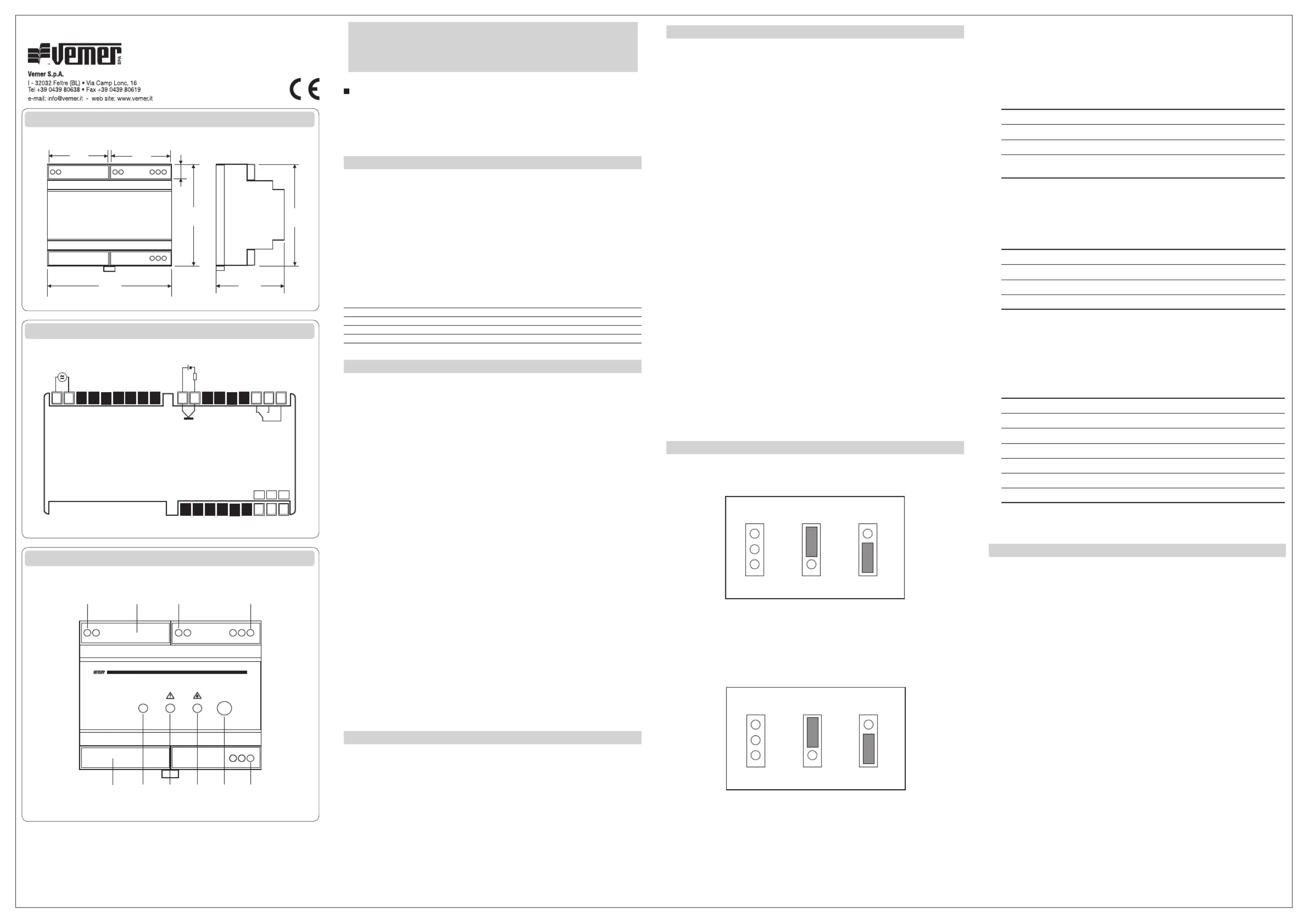
INSTRUMENT DESCRIPTION
Ledpowersupply
Led signaling failure
Led signaling gas alarm
Reset/Testbutton
Powersupplyterminals
Terminals for open collector failure
g
Terminalsforalarmoutputrelay
h
Terminals for gas sensor connection
Set-upjumper
j
Protectionfuse1A
INSTALLATION
Do not use the device in excess of the limits set forth in the technical data. The installer is
responsible for correct, safe installation of the product. Use care during shipping, storage
and handling.
1)Protectionofthedevice.
Toensuretheproperdegreeofprotectionoftheunit,itisnecessarytoinstallthecontrol
unitinanelectricalpanelconstructedinaccordancewithcurrentstandardsforthe
workplace,andinsideofwhichthepowersupplysystemcanalsobehoused.Thecontrol
unitcanbeinstalledatthebottomofthepanelorinDINmodularpanels.
TheLPG,COandCH4Sensorsaredesignedtobewall-mounted(vertically),usingscrews
andplasticplugs.Toproceedwithinstallation,openthecontainerbyunscrewingthe
screwlocatedontheside.Makesurenottodamagethesensorandnottotouchthe
calibration devices.
2)Installationoftheproduct.
Thecorrectinstallationoftheprobeisessentialtoproperoperationofthesystem.
Therefore,itmustbeinstalled:
–Inareaswithcirculationofnaturalair;
–Inareasthatarenotsubjecttodustordirtthatmayrenderthesensorinoperative;
–Nearjetsofwater,intakegrilles,openings,etc;
–Atanadequatedistancefromusersofgassoastopreventthesystemfromintervening
improperlyduetofunctionalleakage.
Also,positioningdependsonthetypeofgastobedetected,specifically:
– CH4 Sensor: Methane gas - at top, about 20-30 cm from the ceiling
– LPG Sensor: LPG - at bottom, about 20-30 cm from the floor
– CO Sensor: carbon monoxide – about 1.5 m from the floor
Fornewsystems,theprobemustbeinstalledaslateaspossible,sothattypical
constructionsiteactivitiesdonotdamagethedetector.
3)Connectionsanduseoftheproduct.
Normalelectricalcablescanbeusedforconnections.Inanycase,wheninstallationis
inplacesthatarestronglyexposedtoelectromagneticdisturbances,itisadvisableto
useshieldedcables.Thedetectionsystemmustalwaysbeinoperation.Therefore,the
electricalpowersupplyofthedetectormustnotincludeswitchesorotherdevicesthat
mayaccidentallyshutitoff.Thepowersupplyofthecontrolunitmustcomplywiththe
requiredvaluesandthecurrentinputofanydeviceconnecttotheterminalsoftherelay
mustbelessthanorequaltothemaximumcapacityofthecontacts.Theaveragelifespan
oftheprobesis5yearsfromthedateofinstallation.Therefore,attheendofthattime
theywillneedtobereplaced.
Attention: make sure you check operation at least once a year, and in any case
whenever there is an extended period of disuse or in the event of replacement.
Any tampering may compromise correct operation of the system.
OPERATION
Oncethedevicehasbeeninstalled,youwillneedtoselecttheoperatinglogicusing
jumperE1.Itcanbeeitherpositiveornegative.Thecontrolunitsignalsitsoperating
statusbymeansofLED’s.
A
Position A
Positive logic
Position B
Negative logic
B
A
B
E1
E1
E1
A
B
DependingonthelogicselectedusingjumperE1,inanormalsituation(noalarms),the
LED’sandtherelaywillbe:
–positivelogic:LEDon,relayenergized
–negativelogic:LEDoff,relayde-energized
Ifnegativeoperatinglogicisselected,thealarmrelaymaybecontrolledinpermanentor
impulsivemode,dependingonthepositionofjumperE2:
A
Position A
Alarm relay
Permanent control
Position B
Alarm relay
Impulsive control
B
A
B
E2
E2
E2
A
B
Oncepoweredon,thecontrolunitperformsthefollowingphasesinsequence:
•Buzzertest(durationabout5seconds)whichcausessequentiallightingoftheLED’sand
abriefringingofthebuzzer.
•Pre-heatingoftheprobe(whichlastsabout1minute),duringwhichthedetection
systemisnotoperationalbecausethisallowstheprobetoreachthecorrectoperating
temperature.
Dimensions
Connection diagram
Description
•Operationaltest(whichlastsabout3minutes)duringwhichthepowersupplyLED
flasheswithafrequencyof2Hzandalltimesettingsareresettozerotomakeiteasierto
checktheprobe.PresstheReset/Testforaboutonesecondtointerrupttheoperational
testphaseandchecktheprobe.
•Gasalarmtest,whichoccursbyplacingthetestspraycanneartheprobeandreleasing
asmallamountofgas.Donotdirectthespraydirectlyontothesensoroftheprobe,
asitmaydamageitirreparably.Thecontrolunitwillsignalthealarminthefollowing
manner:
InterfacePositive logicNegative logic
Led for probe alarm(red)
OffOn
AlarmbuzzerContinuous soundContinuous sound
AlarmrelayDe-energizedEnergized(permanentlyor
in impulsive mode)
PresstheReset/Testkeyforonesecondtosilencethealarm(ifthegasisnolonger
present)andendthetestphase.Torestartthetestphase,pressthecorrespondingbutton
for about 6 seconds.
•Probefailuretest,whichistobesimulatedsimplybydisconnectingtheprobecableand
checkingthefollowingsignals:
InterfacePositive logicNegative logic
Led for probe failure(yellow)
OffOn
AlarmbuzzerIntermittent soundIntermittent sound
FaulureoutputOffOn
Oncethetesthasbeenmade,re-connecttheprobeandpresstheReset/Testbuttonto
restorethecontrolunittonormaloperation.
Normal operation
Duringnormaloperationofthecontrolunit,boththemonitoringforgasalarmandthe
self-diagnosisforplantanomalies(probe)andsystemsanomalies(controlunit)areactive.
Inthisphaseandwithnoalarmsorfailures,thecontrolunitstatusisasfollows:
InterfacePositive logicNegative logic
Led (green)forpowersupply
On On
Led for failure(yellow)
On Off
Led for gas alarm(red)
On Off
AlarmbuzzerNosoundNosound
AlarmrelayDe-energizedEnergized
FaulureoutputOnOff
Inpresenceofgasalarmorprobefailure,thecentralunitgoesintothesameconditions
describedintherelativestestphase.
REFERENCE STANDARDS
ConformitytotheEUdirectives
2006/95/EC(LowVoltage)
89/336/ECmodifiedby92/31/ECCand93/68/EEC(E.M.C.)
isdeclaredwithreferencetothefollowingharmonisedstandard:
EN 61779-1, EN 50270
Produktspecifikationer
| Varumärke: | Vemer |
| Kategori: | gas detektor |
| Modell: | SRG |
Behöver du hjälp?
Om du behöver hjälp med Vemer SRG ställ en fråga nedan och andra användare kommer att svara dig
gas detektor Vemer Manualer

28 Augusti 2025
27 Augusti 2025
27 Augusti 2025
gas detektor Manualer
Nyaste gas detektor Manualer
17 Mars 2026
12 Mars 2026
9 Mars 2026
26 September 2025
25 September 2025
25 September 2025
25 September 2025
25 September 2025
19 September 2025
19 September 2025