Vestil EHLTG-4450-2-36 Bruksanvisning
Vestil ej kategoriserat EHLTG-4450-2-36
Läs gratis den bruksanvisning för Vestil EHLTG-4450-2-36 (12 sidor) i kategorin ej kategoriserat. Guiden har ansetts hjälpsam av 13 personer och har ett genomsnittsbetyg på 5.0 stjärnor baserat på 3 recensioner. Har du en fråga om Vestil EHLTG-4450-2-36 eller vill du ställa frågor till andra användare av produkten? Ställ en fråga
Sida 1/12
Contents:
Warnings & Safety Instructions ........................1
Replacement Parts............................................1
Receiving Instructions .....................................1
Installation Instructions.................................... 2
Operation Instructions ..................................... 3
Routine Maintenance & Safety Checks ........... 4
1
VESTIL MANUFACTURING CORPORATION
P.O. Box 507., Angola, IN 46703 USA
Phone (260) 665-7586 • Fax (260) 665-1339
E-mail: [email protected] • www.vestil.com
OWNER’S
MANUAL
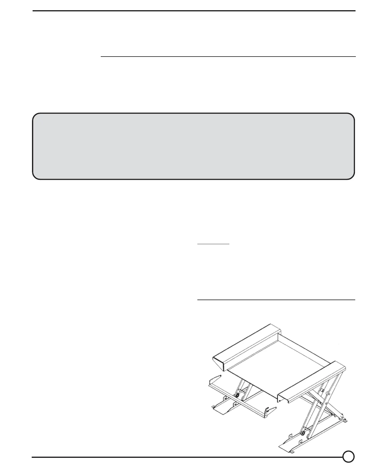
GROUND LIFT SCISSOR TABLES
SERIES EHLTG
Exploded Structural Parts Drawing & BOM......... 5
Electrical & Hydraulic Diagrams & BOM .......6-8
Power Unit’s Operation .................................... 9
Troubleshooting ............................................. 10
Safety Label Identification .............................. 11
Warranty......................................................... 12
RECEIVING INSTRUCTIONS
Every unit is thoroughly tested and inspected prior
to shipment. However, it is possible that the unit could
incur damage during transit.
Inspect the unit closely when it arrives. If you see
evidence of damage or rough handling to either the
packaging or to the product when it is being unloaded,
immediately make a note of it on the Bill Of Lading!
It is important that you remove the product’s packaging
upon its arrival to ensure that there is no concealed dam-
age or to enable a timely claim with the carrier for freight
damage.
Also verify that the product and its specifications are as
ordered.
EHLTG-SERIES
GROUND LIFT
SCISSOR TABLE
Ergonomic Solutions
WARNINGS & SAFETY INSTRUCTIONS
Ensure that all employees understand and follow the following.
•Read and understand the owner’s manual before
using or servicing the lift.
•The load must be removed and either the leg set lowered
onto the maintenance props or the platform fully lowered
to the floor before any work is performed on the hydraulic
system.
•Ensure that all safety and warning labels stay in place
and are legible.
•Do not use the lift if any damage or unusual noise is
observed.
•Always watch the load and around the lift’s sides carefully
when the lift is in operation.
•Do not perform any modifications to the lift without the
manufacturer’s approval. Failure to receive authorization
for changes to the equipment could void the warranty.
•Maintenance and repairs are to be done only by
personnel qualified to perform the required work.
•Do not use brake fluid or jack oils in the hydraulic system.
If oil is needed, use an anti-wear hydraulic oil with a
viscosity grade of 150 SUS at 100°F, (ISO 32 cSt
@ 40°C), or Dexron transmission fluid.
WHEN ORDERING REPLACEMENT PARTS
We take pride in using quality parts on the equipment
we manufacture. We are not responsible for equipment
problems resulting from the use of unapproved
replacement parts.
To order replacement or spare parts for this equipment,
contact the factory.
In any communication with the factory please be pre-pared
to provide the machine’s serial number, which is indicated
on the machine dataplate.
Revised 11-13
04-126-121
A company dedicated to solving ergonomic and material
handling problems since 1955
.
Produktspecifikationer
| Varumärke: | Vestil |
| Kategori: | ej kategoriserat |
| Modell: | EHLTG-4450-2-36 |
Behöver du hjälp?
Om du behöver hjälp med Vestil EHLTG-4450-2-36 ställ en fråga nedan och andra användare kommer att svara dig
ej kategoriserat Vestil Manualer

19 Mars 2026
18 Mars 2026
18 Mars 2026
17 Mars 2026
16 Mars 2026
16 Mars 2026
16 Mars 2026
16 Mars 2026
16 Mars 2026
16 Mars 2026
ej kategoriserat Manualer
Nyaste ej kategoriserat Manualer
3 April 2026
3 April 2026
3 April 2026
3 April 2026
3 April 2026
3 April 2026
3 April 2026
3 April 2026
3 April 2026