Yamaha VXC8-VAW Bruksanvisning
Läs gratis den bruksanvisning för Yamaha VXC8-VAW (1 sidor) i kategorin högtalare. Guiden har ansetts hjälpsam av 18 personer och har ett genomsnittsbetyg på 4.6 stjärnor baserat på 3 recensioner. Har du en fråga om Yamaha VXC8-VAW eller vill du ställa frågor till andra användare av produkten? Ställ en fråga
Sida 1/1
PLEASE READ CAREFULLY BEFORE PROCEEDING
* Please keep this manual in a safe place for future reference.
WARNING
Always follow the basic precautions listed below to avoid the possibility of
serious injury or even death from electrical shock, short-circuiting,
damages, fire or other hazards. These precautions include, but are not
limited to, the following:
•This device contains no user-serviceable parts. Do not open the device or
attempt to disassemble the internal parts or modify them in any way. If it
should appear to be malfunctioning, discontinue use immediately and have it
inspected by qualified Yamaha service personnel.
•Do not expose the device to rain, use it near water or in damp or wet
conditions, or place on it any containers (such as vases, bottles or glasses)
containing liquids which might spill into any openings. If any liquid such as
water seeps into the device, have the device inspected by qualified Yamaha
service personnel.
CAUTION
Always follow the basic precautions listed below to avoid the possibility of
physical injury to you or others, or damage to the device or other property.
These precautions include, but are not limited to, the following:
•Do not place the device in an unstable position where it might accidentally fall
over.
•Do not use the speaker’s handles for suspended installation. Doing so can
result in damage or injury.
•Do not place the device in a location where it may come into contact with
corrosive gases or salt air. Doing so may result in malfunction.
•Always consult qualified Yamaha service personnel if the device installation
requires construction work, and make sure to observe the following
precautions.
-Choose mounting hardware and an installation location that can support the
weight of the device.
-Avoid locations that are exposed to constant vibration.
-Use the required tools to install the device.
-Inspect the device periodically.
•Before connecting the device to other devices, turn off the power for all the
other devices. Before turning the power on or off for all devices, set all volume
levels to minimum.
•Use only speaker cables for connecting speakers to the speaker jacks. Use of
other types of cables may result in fire.
•Do not insert your fingers or hands in any gaps or openings on the device
(ports).
•Do not rest your weight on the device or place heavy objects on it.
•Do not operate the device if the sound is distorting. Prolonged use in this
condition could cause overheating and result in fire.
•Do not pull the cables connected.
•When choosing a power amplifier for use with this device, make sure that the
output power of the amplifier is lower than the power capacity of this device
(see “Specifications”).
Even if the output power of the amplifier is lower than the power capacity of
this device (program), use of excessive input signals resulting in clipping may
cause damage to the device.
Malfunction or fire may occur especially when the following sounds or noises
are generated:
-feedback, when using a microphone
-continuous and extreme volume sound from a musical instrument
-extreme continuous distorted sound
-noise caused by plugging/unplugging the cable while the amplifier is turned
on
Yamaha cannot be held responsible for damage caused by improper use or
modifications to the device.
PRECAUTIONS
Do not open
Water warning
Location
Connections
Handling caution
NOTICE
To avoid the possibility of malfunction/damage to the product or damage to other
property, follow the notices below.
●Handling and maintenance
•Do not expose the device to excessive dust or vibration, or extreme cold or
heat (such as in direct sunlight, near a heater, or in a car during the day), in
order to prevent the possibility of panel disfiguration, unstable operation, or
damage to the internal components.
•Do not place vinyl, plastic or rubber objects on the device, since this might
discolor the panel.
•When cleaning the device, use a dry and soft cloth. Do not use paint thinners,
solvents, cleaning fluids, or chemical-impregnated wiping cloths.
•When turning on the AC power in your audio system, always turn on the
power amplifier LAST, to avoid speaker damage. When turning the power off,
the power amplifier should be turned off FIRST for the same reason.
•Be sure to observe the amplifier’s rated load impedance (see
“Specifications”), particularly when connecting speakers in parallel.
Connecting an impedance load outside the amplifier’s rated range can
damage the amplifier.
•When using a high-impedance speaker connection, make sure the audio
signal is passed through an 80 Hz or above high-pass filter before being input
to the speakers.
•When connecting the speakers with high impedance, be sure that the total
rated input capacity of the speakers does not exceed the output power of the
amplifier.
•Do not swing the speaker by its carrying band.
•Do not place the speaker face down with the grille attached, as deformation of
the grille may result.
•When placing the speaker face down, always place it on a flat and smooth
surface.
•Do not touch the speaker driver unit.
●Protective circuit
This speaker system has an internal protection circuit that shuts off the speaker
unit when an excessive input signal is applied. If the speaker unit emits no
sound, reduce the volume level of the amplifier immediately. The sound will
return automatically in several seconds.
●About this manual
•The illustrations as shown in this manual are for explanation only, and may
appear somewhat different from your device.
•The company names and product names in this manual are the trademarks or
registered trademarks of their respective companies.
Information for Users on Collection and Disposal of Old Equipment
This symbol on the products, packaging, and/or accompanying
documents means that used electrical and electronic products
should not be mixed with general household waste.
For proper treatment, recovery and recycling of old products, please
take them to applicable collection points, in accordance with your
national legislation and the Directives 2002/96/EC.
By disposing of these products correctly, you will help to save
valuable resources and prevent any potential negative effects on
human health and the environment which could otherwise arise from inappropriate
waste handling.
For more information about collection and recycling of old products, please contact
your local municipality, your waste disposal service or the point of sale where you
purchased the items.
[For business users in the European Union]
If you wish to discard electrical and electronic equipment, please contact your dealer
or supplier for further information.
[Information on Disposal in other Countries outside the European Union]
This symbol is only valid in the European Union. If you wish to discard these items,
please contact your local authorities or dealer and ask for the correct method of
disposal.
Supplied Items
Unpack the contents and confirm that all the following items are included.
* Speaker cable and safety wire are not supplied.
Specifications
The specifications data was measured in an anechoic chamber, according to EN 54-24.
Reference axis: Axis is on the center of grille surface and perpendicular to the grille surface.
Reference plane: Plane is on the grille surface and perpendicular to the reference axis.
Horizontal plane: Plane is containing the reference axis and perpendicular to the reference plane.
*1: Half-space (2π)
*2: Calculated based on power rating and sensitivity, exclusive of power compression.
*3: When connecting with low impedance.
*4: 30 mm or less for the Anti-Drop Tab.
The contents of this manual apply to the latest specifications as of the printing date. Since Yamaha makes continuous improvements to the product, this manual
may not apply to the specifications of your particular product. To obtain the latest manual, access the Yamaha website then download the manual file. Since
specifications, equipment or separately sold accessories may not be the same in every locale, please check with your Yamaha dealer.
The dimensions are shown in “Technical Specifications”.
•Speaker × 2•Grille × 2•O-ring × 2
•Tile Rail × 4•Screw (4 × 8) × 12•Cutout Template × 1
•Terminal cover × 2•Owner’s Manual (this manual)•Technical Specifications (English only)
Model
VXC8-VA/VXC8-VAWVXC6-VA/VXC6-VAW
Type2-way, coaxial type, with back can, acoustic suspension
ComponentLF8" (20 cm) cone driver6 1/2" (16 cm) cone driver
HF1" (2.5 cm) soft dome tweeter3/4" (2 cm) soft dome tweeter
Coverage angle (–6 dB)*
1
Horizontal: 180° (500 Hz), 150° (1 kHz), 75° (2 kHz), 55°
(4 kHz)
Vertical: 180° (500 Hz), 150° (1 kHz), 75° (2 kHz), 55° (4
kHz)
Horizontal: 180° (500 Hz), 165° (1 kHz), 95° (2 kHz), 50°
(4 kHz)
Vertical: 180° (500 Hz), 165° (1 kHz), 95° (2 kHz), 75° (4
kHz)
Rated impedance8 Ω (without transformer)
100 V line: 170 Ω (60 W), 330Ω (30 W), 670 Ω (15 W)
70 V line: 80 Ω (60 W), 170 Ω (30 W), 330 Ω (15 W), 670 Ω (7.5 W)
Power ratingNOISE90 W75 W
PGM180 W150 W
MAX360 W300 W
Sensitivity*
1
89 dB (1 W, 1 m, 100 Hz to 10 kHz pink noise)
77 dB (1 W, 4 m, 100 Hz to 10 kHz pink noise)
86 dB (1 W, 1 m, 100 Hz to 10 kHz pink noise)
74 dB (1 W, 4 m, 100 Hz to 10 kHz pink noise)
Maximum SPL*
2
105 dB (60 W, 1 m, 100 Hz to 10 kHz pink noise at 60 W
tap)
93 dB (60 W, 4 m, 100 Hz to 10 kHz pink noise at 60 W
tap)
114 dB (360 W, 1 m, 100 Hz to 10 kHz pink noise at 8 Ω)
102 dB (360 W, 4 m, 100 Hz to 10 kHz pink noise at 8 Ω)
103 dB (60 W, 1 m, 100 Hz to 10 kHz pink noise at 60 W
tap)
91 dB (60 W, 4 m, 100 Hz to 10 kHz pink noise at 60 W
tap)
111 dB (300 W, 1 m, 100 Hz to 10 kHz pink noise at 8 Ω)
99 dB (300 W, 4 m, 100 Hz to 10 kHz pink noise at 8 Ω)
Frequency range (–10 dB)*
1,
*
3
55 Hz – 20 kHz56 Hz – 20 kHz
Crossover frequency3 kHz3.2 kHz
ConnectorCeramic terminal block (3 pin) × 1 (input: +/–, Earth)
Applicable wire size AWG 26–12 (4.0 mm
2
), wire outer diameter Ø6.5 – Ø12.5 mm
Transformer taps70 V60 W, 30 W, 15 W, 7.5 W
100 V60 W, 30 W, 15 W
Overload protectionFull-range power limiting to protect network and transducers
Magnetically shieldedNo
Dust and water resistantIP32 (EN54-24 Enclosure protection rating. Type A: IP21C)
EnclosureBack canSteel (t=1.2 mm), electrodeposition coating, blackSteel (t=1 mm), electrodeposition coating, black
BaffleABS (UL94-5VB), black
GrilleMetal grillePowder coated perforated steel (t=0.6 mm), aperture ratio: 51%
TrimABS
Outer color (grille)VXC8-VA/VXC6-VABlack (approximate value: Munsell N3)
VXC8-VAW/VXC6-VAWWhite (approximate value: Munsell 9.3)
Dimensions (with grille)Ø325 × 295 D mm (Ø12 13/16" × 11 10/16" D)Ø286 × 241 D mm (Ø11 1/4" × 9 8/16" D)
Net weight (with grille, 1 piece)6.6 kg (14.6 lbs)4.4 kg (9.7 lbs)
Cutout sizeØ285 mm (Ø11 1/4")Ø247 mm (Ø9 3/4")
Required ceiling board thickness5 mm – 35 mm*
4
PackagingPackaged in pair
StandardsCertified to the European Standard EN 54-24: 2008 0359-CPR-00405 Certified year: 14
Loudspeaker for voice alarm systems for fire detection and fire alarm systems
Environment type: A
Certified to the European Standard EN60849:1998
Sound systems for emergency purposes
Certified to the International Standard ISO 7240-24: 2010
Sound-system loudspeaker for fire detection and fire alarm systems
In compliance with the British Standard BS-5839-8: 2008 14.8
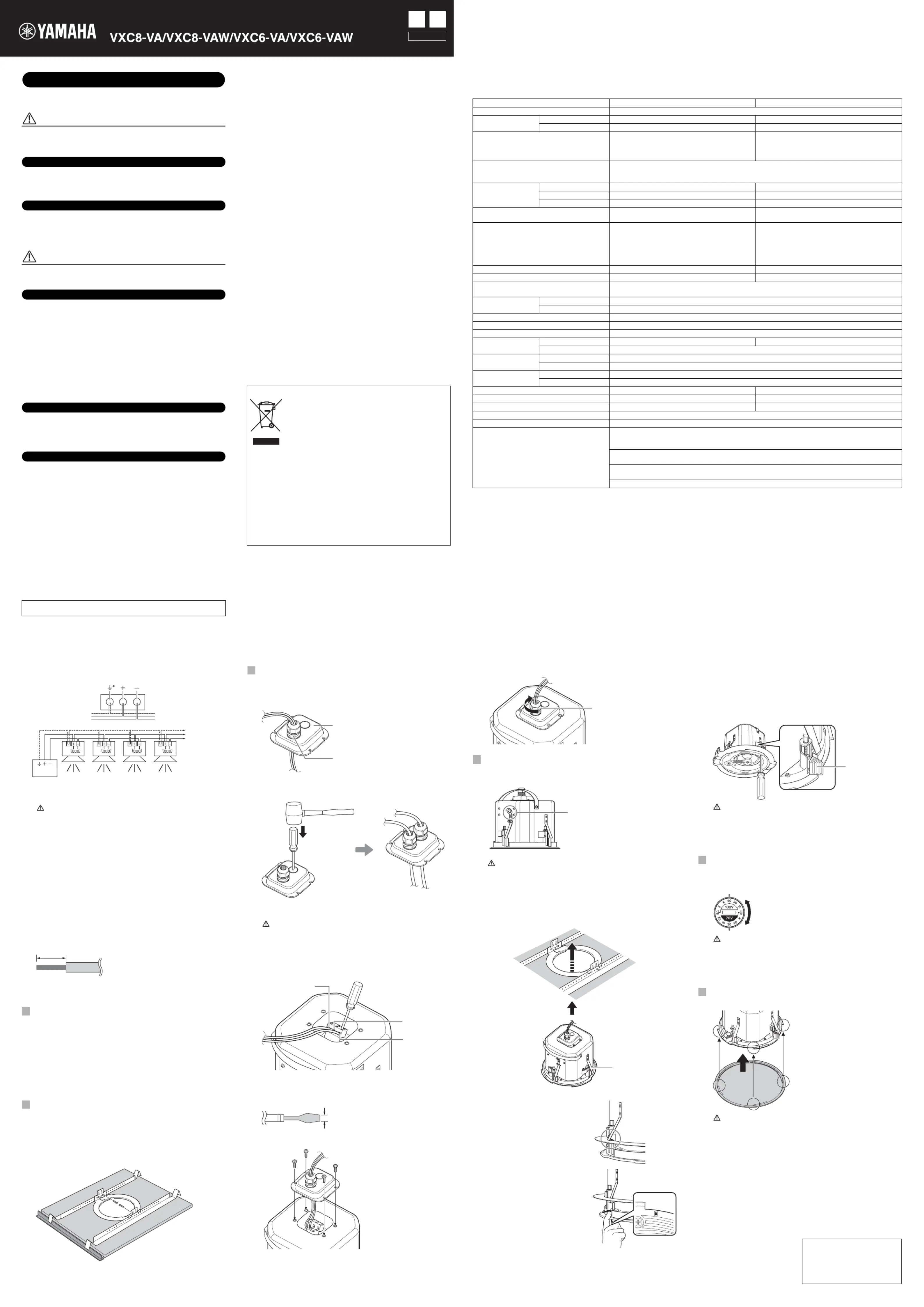
Connecting the Multiple Speakers
When installing the multiple speakers, connect them in parallel way.
CAUTION
When connecting with low impedance, take note of the combined
resistance.
Note
When connecting with high impedance, refer to “Better Sound for
Commercial Installations” (English only) of the Yamaha Pro Audio
web site, at the following URL.
http://www.yamahaproaudio.com/global/en/training_support/
better_sound/
Installing the Speakers
Install the speakers onto the ceiling with the supplied hardware.
Ensure that the strength of the ceiling rail is sufficiently strong.
Illustrations in this manual are for the VXC6-VA. The installation
method is the same for other models.
Pre-installation (Preparation of the Cable)
Use stranded wire for cables attached to the ceramic terminal. Strip
their insulation as shown in the figure and connect them.
Note
Do not plate stranded wires by solder. Doing so will cause the wire to
break.
1.1Put the supplied cutout template to the ceiling and draw a circle by
tracing it.
Make sure to use the cutout template so that hole is the correct
diameter.
Note
If you use a circular cutter, set the diameter with the cutout template.
1.2Cut the hole by tracing the circle.
Be careful to prevent chips or powder entering your eyes while
cutting the hole.
2.1Insert the two tile rails through the cut hole and place them on the
ceiling surface within your reach. Be sure that each tile rails are
oriented as shown below.
2.2Insert the folded O-ring through the cut hole and open it in the ceiling.
2.3Secure the O-ring and tile rails with supplied two screws through
either slot of both O-ring brackets.
1
Cut Out a Hole in the Ceiling
2
Install the Tile Rails and O-ring
From amplifier or
previous speakers
To subsequent
speakers
To
subsequent
speakers
Speaker
Power
amplifier
*You can use this terminal to hook up an earth cable, as
necessary.
About 7 mm (0.3")
20141007
3.1Pull the wiring from the amplifier through the cut hole.
3.2Pass the cables through the cable gland attached to the terminal
cover.
If it is difficult to pass all the cables through a single cable gland, open
the hole in the terminal cover and attach a commercially available
cable gland.
Note
Prepare a cable gland of AVC part no. PGB 13.5-12B.
CAUTION
Use an appropriate tool for opening the hole. Otherwise, you may be
injured if you open the hole with your bare hands.
3.3Loosen the terminal screws of the ceramic terminal with a flat-blade
screwdriver, insert the cables into each terminal and tighten the
screws. Pull on the cables to make sure they are tightly secured and
will not come loose.
Note
Use a flat-blade screwdriver with a blade less than 3 mm (0.1 in.).
3.4Close the terminal cover and tighten the screws.
3
Connecting the Wiring to the Speakers
Cable gland
Terminal cover
*Use the Earth terminal as necessary.
Earth*
+
–
Less than 3 mm (0.1 in.)
3.5Tighten the cap of the cable gland.
4.1Attach the safety wire to the safety wire ring, and connect the wire to
an independent support point, such as a joist.
CAUTION
Always take measures to prevent the speaker falling down.
If the safety wire is too short, prepare another wire appropriate for the
speaker weight and installation conditions. If the wire is too long,
should the speaker fall, the wire may break as a result of too much
strain.
4.2Push up the speaker slowly into the ceiling, taking care not to trap the
cable.
When all the Anti-Drop Tabs cross
over the O-ring, the speaker is held
temporarily.
To release the speaker from the
O-ring, press the Anti-Drop Tabs.
These are located above the U
mark near the edge of the baffle’s
face.
4
Fix the Speakers onto the Ceiling
Cap
Safety wire ring
Anti-Drop Tab
4.3Turn the screwdriver a half turn counterclockwise to loosen the
attachment screw (located beside the U mark). This makes the
clamp easier to align in the channel.
4.4Turn the screwdriver clockwise to tighten the attachment screw.
The first turn of the attachment screw aligns the clamp with the
channel. Further turns move the clamp down the channel to pull the
speaker up into the ceiling.
CAUTION
•Do not over-tighten the attachment screw. Otherwise, the
attachment screw and clamp will break.
•Do not turn any screws other than attachment screw (located
beside the U mark). Otherwise, the speaker may fall or
malfunction.
Select the line voltage/impedance (100V/70V/8Ω) and power tap for
100V/70V line distributed system, by rotating the tap selector switch
on the front side of the speaker with a flat-blade screwdriver.
CAUTION
•The “X” position should not be selected. The 8Ω position should be
selected for 8Ω audio systems only. If the setting is incorrect, it may
cause malfunction of the speaker and amplifier.
•Make sure the amplifier is switched off before operating the tap
selector switch.
Fit the grille to the baffle front and turn it clockwise.
CAUTION
The grille may fall down if it is attached inadequately. Attach it firmly.
The installation is complete.
5
Set the Line Voltage/Impedance and Power
6
Attach the Grille
Clamp
The illustration indicates the setting at 60 W for 100 V
line and 30 W for 70 V line.
Yamaha Pro Audio global web site
http://www.yamahaproaudio.com/
Yamaha Manual Library
http://www.yamaha.co.jp/manual/
Owner’s Manual
Ceiling Speaker
English
ZK28050
ENFR
La version française du Mode d'emploi se trouve au verso.
Produktspecifikationer
| Varumärke: | Yamaha |
| Kategori: | högtalare |
| Modell: | VXC8-VAW |
Behöver du hjälp?
Om du behöver hjälp med Yamaha VXC8-VAW ställ en fråga nedan och andra användare kommer att svara dig
högtalare Yamaha Manualer

24 Mars 2026
31 Augusti 2025
31 Augusti 2025
17 Juni 2025
10 Juni 2025
4 Juni 2025
4 Juni 2025
4 Juni 2025
3 Juni 2025
3 Juni 2025
högtalare Manualer
Nyaste högtalare Manualer
3 April 2026
3 April 2026
2 April 2026
2 April 2026
1 April 2026
1 April 2026
30 Mars 2026
30 Mars 2026
29 Mars 2026
29 Mars 2026