Avtec EA2 UV Bruksanvisning
Avtec
ventilationskåpa
EA2 UV
Läs gratis den bruksanvisning för Avtec EA2 UV (9 sidor) i kategorin ventilationskåpa. Guiden har ansetts hjälpsam av 29 personer och har ett genomsnittsbetyg på 4.7 stjärnor baserat på 15 recensioner. Har du en fråga om Avtec EA2 UV eller vill du ställa frågor till andra användare av produkten? Ställ en fråga
Sida 1/9
OPERATOR MANUAL
IMPORTANT INFORMATION, KEEP FOR OPERATOR
888-994-7636, fax 888-864-7636
uniedbrands.net
PART NUMBER PP MNL1102, REV. C (08/23)
This manual provides information for:
ECOARCH ENERGY EFFICIENT VENTILATION
SYSTEMS
THIS MANUAL MUST BE RETAINED FOR FUTURE REFERENCE. READ,
UNDERSTAND AND FOLLOW THE INSTRUCTIONS AND WARNINGS CONTAINED
IN THIS MANUAL.
FOR YOUR SAFETY Do not store or use gasoline or other ammable vapors
and liquids in the vicinity of this or any other appliance.
NOTIFY CARRIER OF DAMAGE AT ONCE It is the responsibility of the
consignee to inspect the container upon receipt of same and to determine
the possibility of any damage, including concealed damage. Avtec suggests
that if you are suspicious of damage to make a notation on the delivery
receipt. It will be the responsibility of the consignee to le a claim with the
carrier. We recommend that you do so at once.
Manufacture Service/Questions 888-994-7636.
RETAIN THIS MANUAL FOR FUTURE REFERENCE
NOTICE: Due to a continuous program of product improvement, Avtec reserves the
right to make changes in design and specications without prior notice.
NOTICE: Please read the entire manual carefully before installation. If certain
recommended procedures are not followed, warranty claims will be denied.
MODEL NUMBER _________________________
SERIAL NUMBER _________________________
INSTALLATION DATE ______________________
EQUIPMENT DESCRIPTION
This manual covers three of the basic types of systems offered by Avtec:
MODULAR GREASE EXTRACTORS SERIES
Extractor ventilators are listed by UL and are built in accordance of NFPA-96 for
use with UL listed extinguishing systems for duct hood protection. These models
utilize high velocity removable grease extractors. The canopy contains a hidden
grease trough and removable cup. Surface, plenum and duct collar extinguishing
systems may be factory supplied.
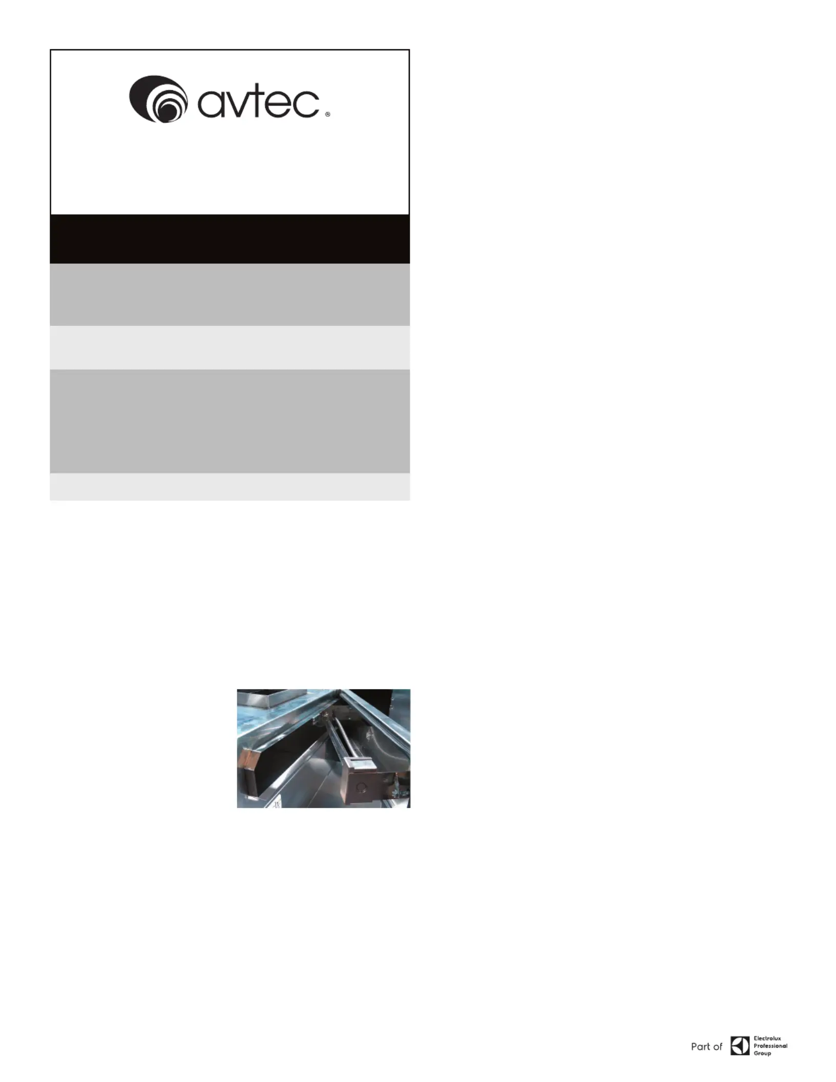
ULTRAVIOLET (UV) SERIES
The EcoArch Energy Efcient Ventilation
UVc is a door assembly integrally
installed in the exhaust plenum of an
EcoArch canopy, consisting of UVc
ltration system designed for use in
the ventilation control of commercial
cooking operations of listed hood
systems. A depiction of this unit is
indicated at left.
The UVc ltration system consists of a Heraus manufactured UVc and Ozone
producing lamp used to reduce exhaust odors and grease deposit emissions
before they enter the exhaust duct system. The UVc light waves and ozone
producing lamp breaks the grease particles into smaller molecules which allow
an Ozone reaction to occur chemically. Like combustion, high temperature
separates the O-atoms in atmospheric Oxygen which then bonds to the grease
molecule causing oxidation. Similarly, in UVc technology, the extra O-atom in the
Ozone splits from the ozone molecule and attaches itself to grease molecule
causing oxidation but without the high temperature, which results in the
reduction of duct cleaning, cleaning costs and risks of potential grease res.
The EcoArch Energy Efcient Ventilation UVc is manufactured with Type 201
Stainless Steel; but, alternatively can be constructed using 200, 300 and 400
series stainless steel without adversely affecting the UVc ltration system
capabilities.
INSTALLATION INSTRUCTIONS
Avtec hoods are provided with adjustable hanging brackets designed to
receive 1/2” threaded rod with a 1/2” nut and washer. Supporting rods must
be connected to all factory supplied/installed brackets. Recommended hanging
height is 78” - 80” above nished oor.
ALL AVTEC VENTILATION SYSTEMS MUST BE INSTALLED IN ACCORDANCE
WITH NFPA-96, REMOVAL OF SMOKE AND GREASE-LADEN VAPORS FROM
COMMERCIAL COOKING EQUIPMENT.
1. Check all local codes prior to installation. Special requirements may be
necessary depending upon building material construction.
2. Move crated hood to location of installation and very carefully uncrate hood.
3. Raise hood to proper hanging height.
4. Suspend hood from adequate roof supports using 1/2” threaded rods with
nuts and washers (See Fig. 1).
5. Level hood left to right and front to back.
6. Brackets are provided for hoods which are to be installed end to end or back
to back.
Bolt brackets together using 3/8” bolt through holes provided (See Fig. 2).
7. Install C channel where the ends of the hood meet and install T moldings on
front face of hoods where they join. High temperature silicone can be used
to install channel and T moldings (See Fig. 3).
Information contained in this document is known to be current and accurate at the time of printing/creation. Reference our product line website for the most updated product information and
specications. © 2023 Electrolux Professional, Inc. All Rights Reserved.
Produktspecifikationer
| Varumärke: | Avtec |
| Kategori: | ventilationskåpa |
| Modell: | EA2 UV |
Behöver du hjälp?
Om du behöver hjälp med Avtec EA2 UV ställ en fråga nedan och andra användare kommer att svara dig
ventilationskåpa Avtec Manualer

1 September 2025
1 September 2025
31 Augusti 2025
ventilationskåpa Manualer
- Cecotec
- Ersa
- Hoover
- Defy
- Whirlpool
- Apelson
- NuTone
- Infiniton
- Big Chill
- FAR
- Saba
- Schweigen
- LG
- Kenmore
- Hisense
Nyaste ventilationskåpa Manualer
23 Oktober 2025
21 Oktober 2025
19 Oktober 2025
19 Oktober 2025
19 Oktober 2025
18 Oktober 2025
18 Oktober 2025
18 Oktober 2025
17 Oktober 2025
16 Oktober 2025