Block PVSE 400/24-20 Bruksanvisning
Block Inte kategoriserad PVSE 400/24-20
Läs gratis den bruksanvisning för Block PVSE 400/24-20 (2 sidor) i kategorin Inte kategoriserad. Guiden har ansetts hjälpsam av 36 personer och har ett genomsnittsbetyg på 4.2 stjärnor baserat på 8 recensioner. Har du en fråga om Block PVSE 400/24-20 eller vill du ställa frågor till andra användare av produkten? Ställ en fråga
Sida 1/2
Sicherheitsmaßnahmen vor der Installation
Das Betriebsmittel ist vor unzulässiger Beanspruchung zu schützen.
Insbesondere dürfen bei Transport und Handhabung keine Bauele-
mente verbogen und/oder Isolationsabstände verändert werden. Die
Berührung elektrischer Bauelemente und Kontakte ist zu vermeiden.
Betriebsmittel immer im spannungsfreien Zustand montieren und
verdrahten. Die Produktbeschreibung und die technischen Hinweise in
unserem Hauptkatalog sowie die Aufschriften am Betriebsmittel und
auf dem Typenschild sind zu beachten.
Installation
Die Installation ist entsprechend den örtlichen Gegebenheiten,
einschlägigen Vorschriften (z. B. VDE 0100), nationalen Unfallverhü-
tungsvorschriften (z. B. UVV-VBG4 bzw. BGV A2) und den anerkannten
Regeln der Technik durchzuführen. Dieses elektrische Betriebsmittel
ist eine Komponente, die zum Einbau in elektrische Anlagen oder
Maschinen bestimmt ist und erfüllt die Anforderungen der Niederspan-
nungsrichtlinie (73/23/ EWG). Der geforderte Mindestabstand vom
10 mm zu benachbarten Teilen ist unbedingt einzuhalten, um die Küh-
lung nicht zu behindern! Bei Einbau in Maschinen ist die Aufnahme des
bestimmungsgemäßen Betriebes solange untersagt, bis festgestellt
wurde, dass die Maschine den Bestimmungen der Maschinenrichtlinie
(89/392/EWG) entspricht; EN 60204 ist zu beachten. Die Aufnahme
des bestimmungsgemäßen Betriebes ist nur bei Einhaltung der EMV-
Richtlinie (89/336/EWG) erlaubt. Die Einhaltung der durch die EMV-
Gesetzgebung geforderten Grenzwerte liegt in der Verantwortung des
Herstellers der Anlage oder Maschine.
Installation
Anschluss
1
2
3
4
1
2
3
4
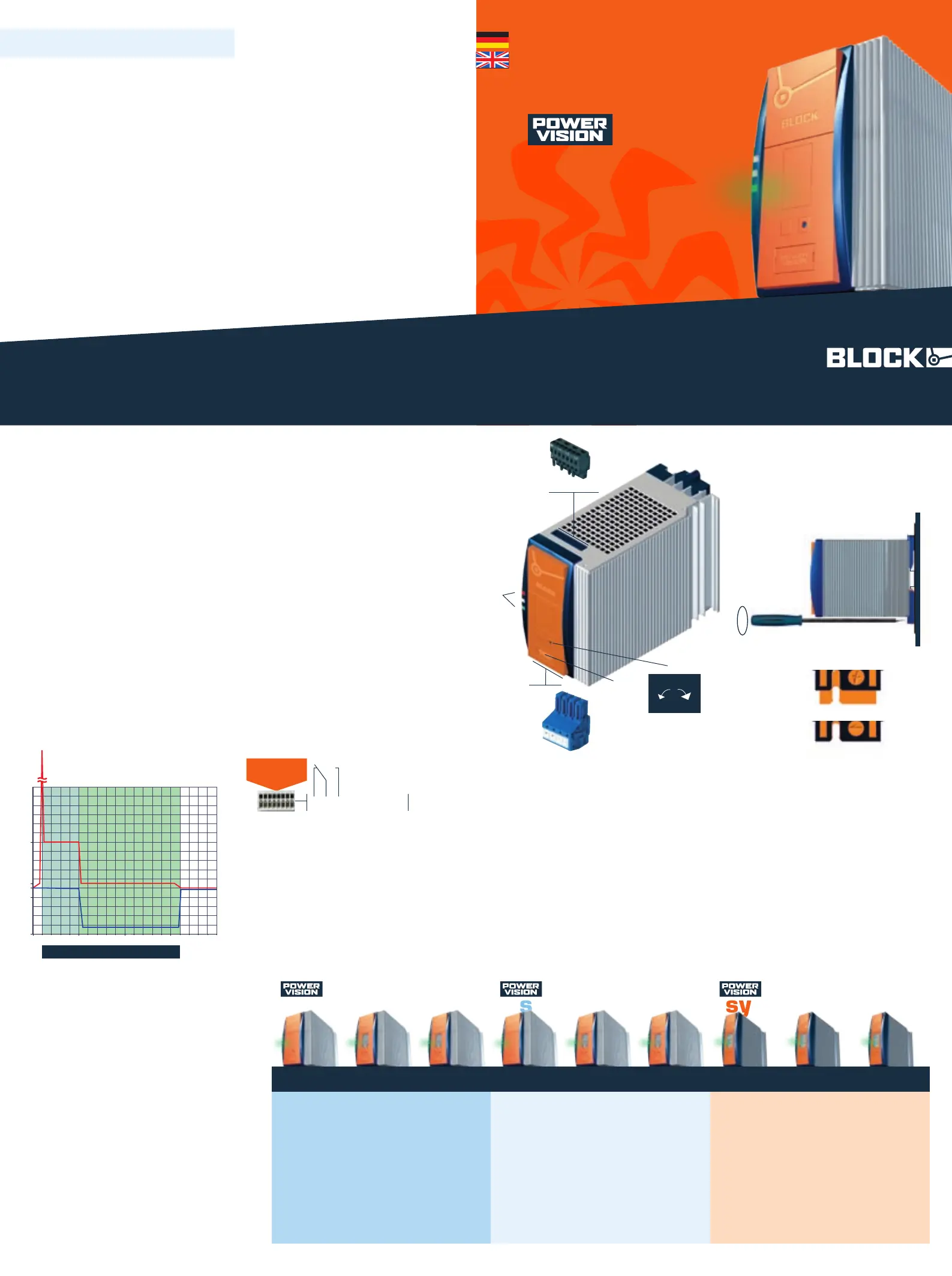
LEDs: Die grüne LED (a) leuchtet, sofern die Ausgangsspannung
größer als ca. 20,4 Vdc ist. Die rote LED (b) leuchtet, sofern die
Ausgangsspannung kleiner als ca. 20,4 Vdc ist.
Ausgangsspannung: Die Ausgangsspannung kann mit einem
Schraubendreher verändert werden. Drehung im Uhrzeigersinn
erhöht die Ausgangsspannung. Drehung gegen den Uhrzeigersinn
verringert die Ausgangsspannung.
Eingang(schwarzer Stecker) line
Ausgang(blauer Stecker) load
Montage: PVSE mit geöffneter Schließnocke (6a) im rechten
Winkel auf die Tragschiene TH35 setzen. Befestigung mit Schrau-
bendreher im Uhrzeigersinn schließen (6b).
Überstromverhalten: Real Power Boost und Top Boost.
Power Good-Ausgang: nur bei den Ausführungen
PVSE-400/24-x0A und PVSE-400/24-x0Z erhältlich.
Die Schutzkappe ist zur Vermeidung statischer Entladungen nur
unter Anwendung von ESD-Schutzmaßnahmen abzunehmen.
6
PE L1 L2 L3
a
b
BLOCK Transformatoren-Elektronik GmbH & Co. KG
Max-Planck-Straße 36–46
27283 Verden
Germany
Phone +49 4231 678-0
Fax +49 4231 678-177
www.block-trafo.de
www.pv400.de
Technische Änderungen vorbehalten.
Subject to change.
KAPVSE 10.08.PDF.0 Printed in Germany
Download der ausführlichen Betriebsanleitung unter: www.pv400.de
Download the complete user manual at www.pv400.de
www.pv400.de
KAPVSE 2008•10
line
5
7
1
2
3
4
65
7
Abbildung zeigt den PVSE 400/24-20
This figure shows the PVSE 400/24-20
+ + – –
load
Connection
Safety measures before installation
This equipment is to be protected against improper use. Components
are not to be bent or isolation spacing changed, especially through
handling and transport. The contact with electrical components and
terminals is to be avoided. Always disconnect the equipment from the
mains supply, before commencing installation or wiring. The product
description, technical information in our main catalogue and the mar-
king on the equipment ratings plate are to be observed.
Installation
Installation must be carried out according to the prevailing local
conditions and safety regulations (e.g. VDE 0100) national accident
prevention regulations (e.g. UVV-VBG4 or BGV A2) and the generally
accepted rules of technology. This equipment is a component designed
for installation into electrical systems and machines, and fulfils the
requirements of the low voltage guidelines (73/23/EWG). The required
min spacing of 10 mm to neighbouring components must be observed
to guarantee the required cooling. When installed into machinery, the
normal operation is forbidden until it is determined that the machine
fulfils the requirements of the machinery guidelines (89/392/EWG).
EN 60204 must be observed. The EMC requirements must be fulfilled
before operation is commenced. The observance of the required limita-
tions for the EMC legislation is the responsibility of the manufacturer of
the installation or machinery.
Installation
T
To reduce the risk of mistaking the terminals, the supplied
terminals must be used.
LEDs: The green LED (a) lights as soon as the output voltage is
larger than approx. 20,4 Vdc. The red LED (b) lights if the output
voltage is lower than 20,4 Vdc.
Output voltage: The output voltage can be altered using a scre-
wdriver. Turning the adjustment screw clockwise raises the output
voltage. Turning the adjustment screw anticlockwise reduce the
output voltage.
Input (black plug) line
Output (blue plug) load
Mounting: Place the PVSE with opened cam lock (6a) in a 90°
angle on the DIN 35 mm rail and close the cam lock in a clockwise
direction with a screwdriver (6b).
Overload current behaviour: Real Power Boost and Top Boost.
Power Good output: Only available with the models PVSE-A and
PVSE-Z .
The protective cap is to reduce the risk of static discharge and
should only be removed with the use of ESD protective measures.
PVSE
Stabilisierte Stromversorgung, Economy
Stabilised economic power supply
block-trafo.de
T
Um Verwechslungen mit anderen Anschlüssen zu ver-
meiden, verwenden Sie ausschließlich die mitgelieferten
Stecker.
system-modulessemistabilisedstabilised
PVSEPVSBPVSLPVEPVBPVLPVUPVRPVF
Stabilisierte Strom-
versorgung, Economy
Stabilised economic
power supply
PVSE 400/24-10
PVSE 400/24-20
PVSE 400/24-40
Stabilisierte Strom-
versorgung, Basic
mit integrierter
Kontrolleinheit
Stabilised basic power
supply with integrated
control module
PVSB 400/24-10
PVSB 400/24-20
PVSB 400/24-40
Stabilisierte Strom-
versorgung mit
integrierter
Kontrolleinheit und
Netzeingangsüber-
wachung
Stabilised power
supply with integrated
control module and
line monitor
PVSL 400/24-10
PVSL 400/24-20
PVSL 400/24-40
Semistabilisierte
Stromversorgung,
Economy
Semi stabilised
economic power
supply
PVE 400/24-10
PVE 400/24-20
PVE 400/24-40
Semistabilisierte
Stromversorgung,
Basic mit integrierter
Kontrolleinheit
Semi stabilised basic
power supply with
integrated control
module
PVB 400/24-10
PVB 400/24-20
PVB 400/24-40
Semistabilisierte
Stromversorgung mit
integrierter
Kontrolleinheit und
Netzeingangsüber-
wachung
Semi stabilised power
supply with integrated
control module and
line monitor
PVL 400/24-10
PVL 400/24-20
PVL 400/24-40
PVUA 24/24-10
PVUC 24/24-10
PVUC 24/24-20
PVA 24/3,2 Ah
PVA 24/7 Ah
Redundanzmodul mit
2 Eingängen für
24-V-Umgebung
Redundancy module
for 24 V supply with
two inputs
PVRE 24/24-20
PVRB 24/24-20
Elektronischer
Schutzschalter mit
4 Kanälen für 24-V-
Umgebung
Electronic fuse unit of
up to four channels
for 24 V
PVFE 24/24-24
PVFE 24/24-40
PVFB 24/24-32
PVUA Unterbre-
chungsfreie Strom-
versorgung
Uninterruptible power
supply
PVUC Kapazitives
Puffermodul
Capacitive buffer
module
PVA Akku-Block
Akkumulator
t [sec] ü
I
out
[%] ü
U
out
[V]
ü
0
0 5
≈
Top Boost
INENN + 60 A
Real
Power
Boost
Überstrom
Overload current
7
Strombegrenzung
ü
ü
TH35
5
a
b
6
8
8
inkl. incl.:
PVSE 400/24-x0A
PVSE 400/24-x0Z
88
U
out
+–
12345678
Relais aktiv (Kontakt 2-3 geschlossen),
wenn Uout > typ. 20,4 Vdc.
Relay active (contact 2-3 closed),
if Uout > typ. 20,4 Vdc.
Produktspecifikationer
| Varumärke: | Block |
| Kategori: | Inte kategoriserad |
| Modell: | PVSE 400/24-20 |
Behöver du hjälp?
Om du behöver hjälp med Block PVSE 400/24-20 ställ en fråga nedan och andra användare kommer att svara dig
Inte kategoriserad Block Manualer

24 September 2024
24 September 2024
24 September 2024
24 September 2024
21 September 2024
18 Augusti 2024
Inte kategoriserad Manualer
Nyaste Inte kategoriserad Manualer
9 April 2025
9 April 2025
9 April 2025
9 April 2025
9 April 2025
9 April 2025
9 April 2025
9 April 2025
9 April 2025
9 April 2025