Canarm IDB1210150 Bruksanvisning
Canarm hushålls fläkt IDB1210150
Läs gratis den bruksanvisning för Canarm IDB1210150 (8 sidor) i kategorin hushålls fläkt. Guiden har ansetts hjälpsam av 30 personer och har ett genomsnittsbetyg på 4.2 stjärnor baserat på 2 recensioner. Har du en fråga om Canarm IDB1210150 eller vill du ställa frågor till andra användare av produkten? Ställ en fråga
Sida 1/8
200 & IDB SERIES
INLINE DUCT BLOWERS
OPERATION INSTRUCTIONS AND PARTS MANUAL
PLEASE READ AND SAVE THESE INSTRUCTIONS
200 SERIES MODELS: 207, 209, 210, 212, 215, 218
IDB SERIES MODELS: IDB07, IDB09, IDB10, IDB12, IDB15, IDB18
GENERAL SAFETY
Rotating parts, (pulleys, shafts and belts) on fans should not be exposed. Where these components are not protected by ductwork, cabinets
or covers, appropriate guards should be employed to restrict exposure to rotating parts. Access doors should not be opened with the fan
operating to avoid foreign objects being drawn into the system. On initial start-up, a careful inspection should be carried out to ensure no
foreign material is present which could become airborne in the system.
Read installation and operation instructions carefully before attempting to install, operate or service Canarm/Delhi 200 Series or
Canarm/Delhi IDB Series Blowers. Failure to comply with instructions could result in personal injury and/or property damage. Retain
instructions for future reference.
BEFORE YOU BEGIN
Inspect unit for damage, report any shipping damage to carrier. Check all fasteners, re-tighten as required. Rotate the blower wheel by
hand to ensure free rotation. If rubbing occurs, loosen the set screw(s), re-position the wheel to the shaft center, re-tighten set screws.
INSTALLATION
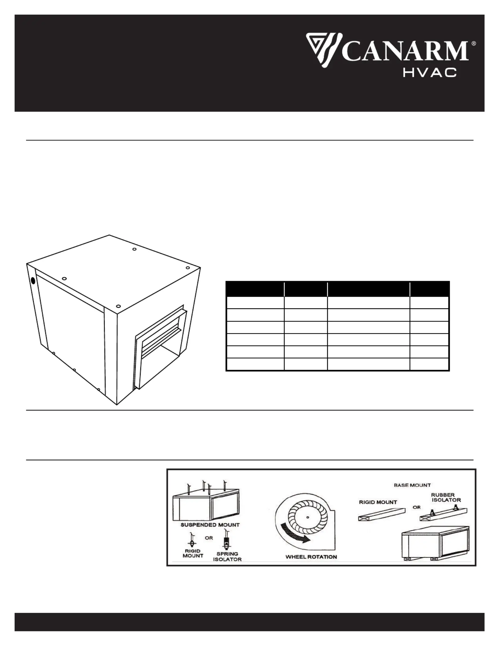
SUSPENSION MOUNTING
Suspend the unit using 4 threaded rods
through the (4) 7/8" clearance holes
located at the top of the unit
(see Figure 1) or by an angle iron cradle
(supplied by others) under the unit.
MODELWEIGHTMAX. HPSHAFT DIAMETER
207, IDB073/43/4"43 lbs
209, IDB093/43/4"55 lbs
210, IDB101 1/23/4"65 lbs
212, IDB121 1/23/4"82 lbs
215, IDB1531"140 lbs
218, IDB1851"158 lbs
FIGURE 1
BASE MOUNTING
Secure unit through the 4 internal 7/8" clearance holes to a solid base. Ensure unit is level. Complete installation of inlet & outlet ducts.
NOTE: Flexible inlet & outlet duct collars are recommended to minimize vibration transmission.
200_IDB-M-03_07_22Page 1 of 4
Produktspecifikationer
| Varumärke: | Canarm |
| Kategori: | hushålls fläkt |
| Modell: | IDB1210150 |
Behöver du hjälp?
Om du behöver hjälp med Canarm IDB1210150 ställ en fråga nedan och andra användare kommer att svara dig
hushålls fläkt Canarm Manualer

22 September 2025
21 September 2025
21 September 2025
21 September 2025
20 September 2025
20 September 2025
20 September 2025
20 September 2025
11 September 2025
10 September 2025
hushålls fläkt Manualer
Nyaste hushålls fläkt Manualer
1 April 2026
1 April 2026
26 Mars 2026
26 Mars 2026
25 Mars 2026
25 Mars 2026
24 Mars 2026
23 Mars 2026
22 Mars 2026
22 Mars 2026