EBERLE HYG-E 6001 Bruksanvisning
EBERLE Klimatkontroll HYG-E 6001
Läs gratis den bruksanvisning för EBERLE HYG-E 6001 (2 sidor) i kategorin Klimatkontroll. Guiden har ansetts hjälpsam av 33 personer och har ett genomsnittsbetyg på 4.6 stjärnor baserat på 4 recensioner. Har du en fråga om EBERLE HYG-E 6001 eller vill du ställa frågor till andra användare av produkten? Ställ en fråga
Sida 1/2
1. Funktion
a)Die Hygrostate der Typen HYG-E 6001, HYG-E
7001/7005, und HYG 4003 eignen sich für den
automatischen Betrieb einer Be- oder Ent-
feuchtungsanlage.
b)Der HYG-E 7001/7005 ist eine Kombination
Hygrostat und Raumtemperaturregler für den
Einsatz in Schwimmbäder etc.
2. Elektrischer Anschluß
Schließen Sie alle Leitungen genau nach dem
Schaltbild im Gehäusedeckel an.
Diese Geräte dürfen nur durch einen Fachmann gemäß dem
Schaltbild im Gehäusedeckel installiert werden. Dabei sind
die bestehenden Sicherheitsvorschriften zu beachten.
Ö
wird durch entsprechenden Einbau (nach VDE 0100)
und der Montage auf einen ebenen, nichtleitenden und
nichtbrennbaren Untergrund erfüllt.
Diese unabhängig montierbaren Geräte dienen zur
Regelung der Feuchte bzw. der Temperatur ausschließlich
in trockenen und geschlossenen Räumen mit üblicher
Umgebung. Außerdem sind sie gemäß VDE 0875 bzw EN
55014 funkentstört und arbeiten nach der Wirkungsweise
1C.
4. Technische Daten
Achtung: Über AC24V nur in trockenen Räumen! Räumen (max 95%, nicht kondensierend)!
Nicht geeignet z.B. für Gärschränke oder ähnliche Einrichtungen.
HYG-E 7001HYG-E 7005HYG-E 6001HYG 4003
Hygrostat
Einstellbereich35–100% r.F.35–100% r.F.30–100% r.F.
bei HYG 7005 unter d. Deckel
Schaltdifferenzca. 4%ca. 4%ca. 5%
Betriebsspannung24…230V AC24…230V AC24…230V AC
Schaltstrom5 (0,2)A AC;5 (0,2)A AC;15 (2) A
55W DC55W DC
Kontakt1 Wechsler1 Wechsler1 Wechsler
Temperaturregler
Einstellbereich10–35°C––
Schalttemperatur-Differenzca. 0,6K––
BetriebsspannungAC 24/230V––
SchaltstromHeizen10 (4) A––
Kühlen5 (2) A––
Kontakt1 Wechsler––
Thermische Rückführungserienmäßig––
SchalterNetz Ein/Aus––
HYG 7005 ohne Netzschalter
SchutzartIP 30IP 30IP 54
Umgebungstemperatur0…55°C0…55°C0…60°C
Kabellänge–––
Zulässige Luftgeschwindigkeit––8m/sec.
4. Specification
Attention: For more than AC 24V only in dry rooms (max. 95% without condensation).
Not suitable e.g. for brew cabinets or similar equipment
HYG-E 7001HYG-E 7005HYG-E 6001HYG 4003
Hygrostat
Setting range35–100% r.F.35–100% r.F.30–100% r.F.
HYG 7005 below cover
Switching diff.approx. 4%approx. 4%approx. 5%
Operating voltage24…230V AC24…230V AC24…230V AC
Switching current5 (0,2)A AC;5 (0,2)A AC;15 (2) A
55W DC55W DC
Contact1 c/o1 c/o1 c/o
Thermostat
Setting range10–35°C––
Switching temp. diff.approx. 0,6K––
Operating voltageAC 24/230V––
Switching currentheating10 (4) A––
cooling5 (2) A––
Contact1 c/o––
Thermal feedbackstandard––
Switch Mains ON/OFF––
HYG 7005 without mains switch
Degree of protectionIP 30IP 30IP 54
Ambient temperature0…55°C0…55°C0…60°C
Cable length–––
Admissible air speed––8m/sec.
3. Montage
HYG-E 7001/7005, HYG-E 6001
– Es ist darauf zu achten, daß die Geräte nicht
einer direkten Wassereinwirkung ausgesetzt
sind, z.B. Spritzwasser beim Schwimmbad usw.
– Der Hygrostat ist waagrecht, in Augenhöhe zu
montieren.
– Der Kabelaustritt aus der Wand ist bei den
Typen HYG-E7001/7005, HYG-E6001 unbe-
dingt zu verputzen oder anderweitig, mit
Ausnahme von Silikon und silikonhaltigen
Materialien abzudichten.
HYG 4003
Der Hygrostat wird nach Möglichkeit im Abluft-
oder Umluftkanal vor dem Ventilator waagrecht
montiert. Max. zulässige Luftgeschwindigkeit
8m/sec.
U 468931022899
Montage- und
Bedienungsanleitung
Hygrostate
1. Function
a)The HYG-E 6001, HYG-E 7001/7005 and HYG
4003 Hygrostats are suitable for the automatic
operation of a humidification and dehumidifica-
tion equipment.
b)The HYG-E 7001/7005 is a combination of a
hygrostat and a room temperature controller for
use in swimming-pool halls, etc.
2. Electric supply
Connect all lines exactly according to the wiring
diagram shown in the case cover.
These units must be mounted by an expert, according to
the wiring diagram inside the housing cover. The existing
safety regulations must be observed.
Ö
Will be met by corresponding installation (acc. to VDE
0100) and by fitting on smooth and non-conductive
and non-flammable surface.
These units which can be mounted independently are for
controlling of humidity or ambient temperature in dry and
enclosed rooms only with normal environment.
They have radio interference suppression in accordance
with VDE 0875 or EN 55014 and operate to efficiency 1C.
3. Installation
HYG-E 7001/7005, HYG-E 6001
– Make sure the units are not exposed to direct
water effects, such as water jets in pool halls.
– Install the hygrostat in a horizontal position, at
the eye level.
– Plaster the spot where the cable leaves the
wall or seal otherwise when using the types
HYG-E 7001/7005, HYG-E 6001. Do not use
silicone or silicone-containing materials.
HYG 4003
Install the hygrostat in the foul air or recircula-
tion duct after the fan, if possible. Max admis-
sible air speed: 8m/sec.
Installation and
Operating Instructions
Hygrostate
HYG-E 7001/7005HYG-E 6001HYG 4003
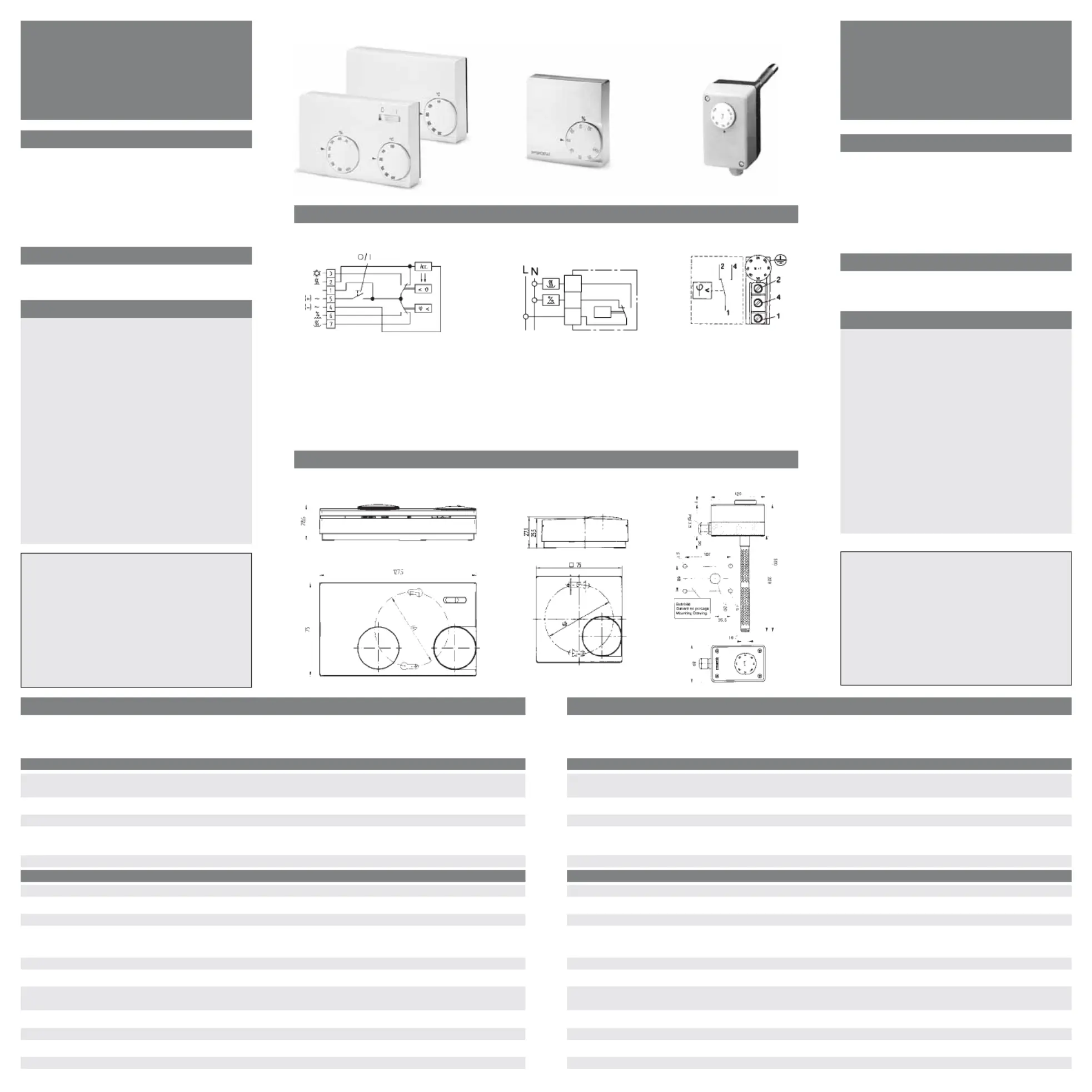
Schaltbild / Wiring Diagram
HYG-E 7001/7005HYG-E 6001HYG 4003
Maße / Dimensions
HYG-E 7001/7005HYG-E 6001HYG 4003
Klemme 1–4Befeuchten
Klemme 1–2Entfeuchten
terminal 1–4humidify
terminal 1–2dehumidify
Achtung:Über AC24V nur in
trockenen Räumen!
Attention:For more than AC 24V only
in dry rooms!
Klemme 1–2Entfeuchten
Klemme 1–3Befeuchten
terminal 1–2dehumidify
terminal 1–3humidify
Hygrostat:Klemme 1/5–6Befeuchten
Klemme 1/5–7Entfeuchten
Temperaturregler:Klemme 1/5–2Heizen
Klemme 1/5–3Kühlen
Hygrostat:terminal 1/5–6humidify
terminal 1/5–7dehumidify
Temp.controller terminal 1/5–2heating
terminal 1/5–3cooling
1
3
2
>
ϕ
Irrtum und Änderung vorbehalten
Produktspecifikationer
| Varumärke: | EBERLE |
| Kategori: | Klimatkontroll |
| Modell: | HYG-E 6001 |
| Bredd: | 750 mm |
| Djup: | 75 mm |
| Höjd: | 25.5 mm |
| Bildsensortyp: | Syntetfiber |
| Spänning: | 24 - 230 V |
| Kontrolltyp: | Rotations- |
| Hysteres: | -4 % |
| Kopplingsschema: | Ja |
| Intervall för relativ operativ luftfuktighet: | 35 - 100 % |
| Internationellt skydd (IP) kod: | IP30 |
| Ingående ström: | 5 A |
| Höljefärg: | Vit |
Behöver du hjälp?
Om du behöver hjälp med EBERLE HYG-E 6001 ställ en fråga nedan och andra användare kommer att svara dig
Klimatkontroll EBERLE Manualer

24 Augusti 2025
26 Augusti 2024
Klimatkontroll Manualer
Nyaste Klimatkontroll Manualer
22 Februari 2026
9 Oktober 2025
29 September 2025
7 September 2025
7 September 2025
7 September 2025
7 September 2025
7 September 2025
7 September 2025
6 September 2025