EBERLE TR 52483 Bruksanvisning
EBERLE ej kategoriserat TR 52483
Läs gratis den bruksanvisning för EBERLE TR 52483 (4 sidor) i kategorin ej kategoriserat. Guiden har ansetts hjälpsam av 26 personer och har ett genomsnittsbetyg på 4.3 stjärnor baserat på 6 recensioner. Har du en fråga om EBERLE TR 52483 eller vill du ställa frågor till andra användare av produkten? Ställ en fråga
Sida 1/4
TR 524 83 TR 524 83
Elektronischer einstufiger Thermostat / Electronic single-step thermostat
MONTAGEANLEITUNG
Anwendung
−Ventilatorschaltung
−Elektro-Direktheizungen
−Ventilschaltung von
Warmwasser- und Gasheizungen
−Kleinwärmepumpen
−Kältetechnik
ZUR BEACHTUNG
Installationsanleitung
Nur für den Elektroinstallateur!
Fehler beim Anschluss können zur
Beschädigung des Regelgerätes
führen! Für Schäden, die durch
falschen Anschluss und/oder
unsachgemäße
Handhabung
entstehen, wird nicht gehaftet!
MOUNTING INSTRUCTION
Application
−Fan circuits
−Electric direct heating
−Valve circuits of hot water-
and
gas heatings
−Small-type heat pumps
−Refrigeration technology
ATTENTION
Instruction for installation for
the electrician, only!
Faulty connection may lead to
damages of the controller! We
accept no liability for damages
caused by false installation and/or
improper handling!
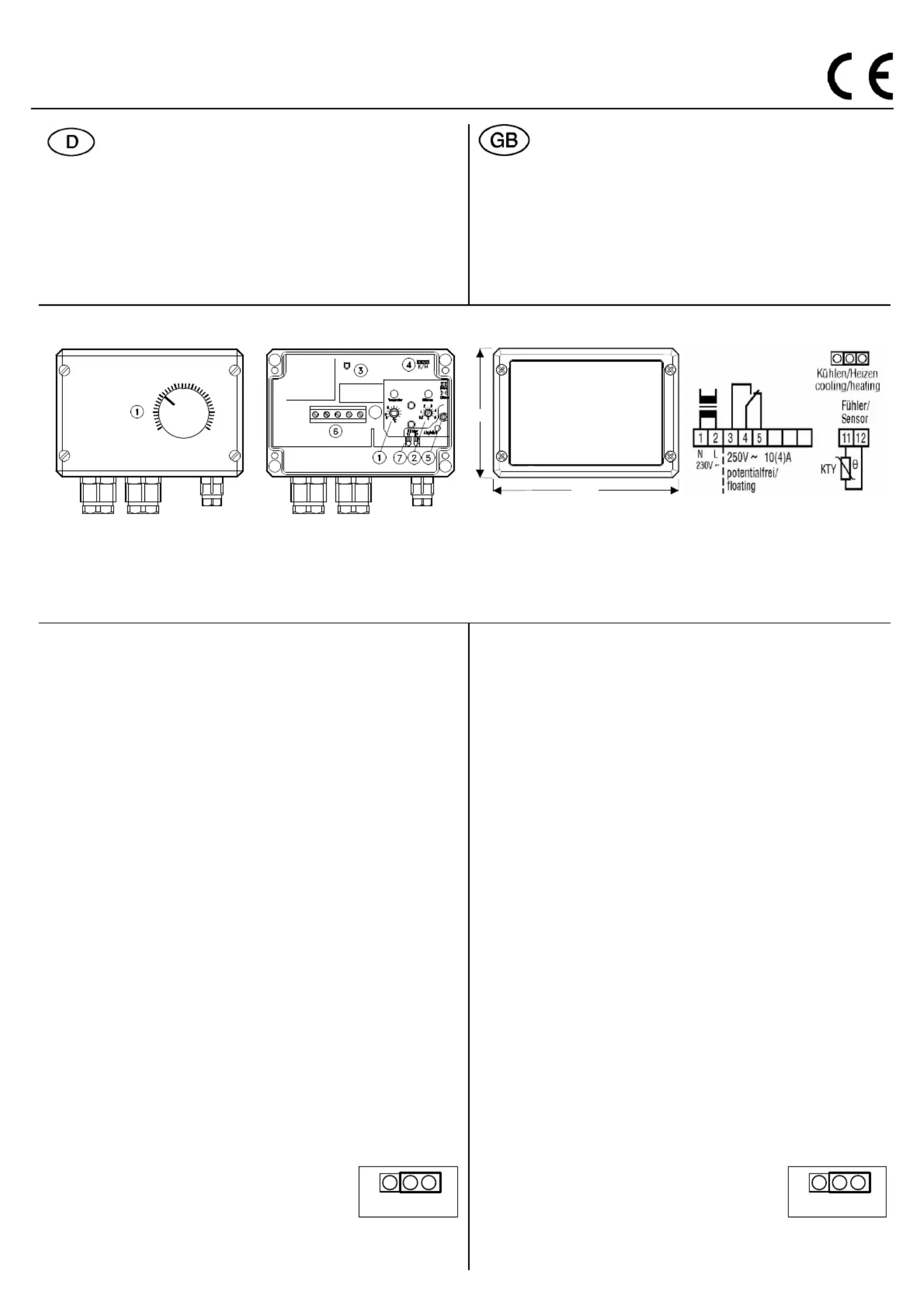
Bedienelemente
Control
Befestigung
Installation
125
85
Anschluss
Connection
1 Einstellknopf Solltemperatur
2 Einstellung Schaltdifferenz
3 Schaltzustandsanzeige des Relais (LED)
4 Steckbrücke „Heizen“/„Kühlen“
5 Einstellung Fühlerabgleich
6 Anschlussklemmen Netz und Last
7 Anschlussklemmen für den Fühler
1 Adjusting knob nominal temperature
2 Adjustment operating differential
3 Indication of adjustment state of relay (LED)
4 Plug bridge „heating“ / „cooling“
5 Adjustment sensor balancing
6 Terminals for power line (N) and load (L)
7 Terminals for the sensor
Installationshinweise
1. Kurzbeschreibung
Der Regler erfasst mit einem Temperaturfühler die Isttemperatur an
einem Messort und schaltet in Abhängigkeit der Abweichung zur
Solltemperatur ein Relais.
2. Funktion
Weicht die Isttemperatur von der eingestellten Solltemperatur ab, wird
ein Relais geschaltet. Die Schaltpunkte ergeben sich aus der
Solltemperatur +/- der Schaltdifferenz.
Über eine interne Steckbrücke kann zwischen der Funktion „Heizen"
oder „Kühlen" gewählt werden.
Der Schaltzustand des Relais wird durch eine rote LED im Gerät
angezeigt
(LED an = Relais eingeschaltet).
2.1. Solltemperatur
Die gewünschte Temperatur kann im Bereich von 0..50°C eingestellt
werden.
2.2. Schaltdifferenz
Die Schaltdifferenz (Abstand zwischen Ein- und Ausschalttemperatur)
kann an einer internen Drehwelle (Differenz) eingestellt werden.
2.3. Fühlereingang
DerTemperaturfühler wird an den dafür vorgesehenenKlemmen (11, 12)
angeschlossen. Dabei muss nicht auf die Polung geachtet werden. Die
maximale Leitungslänge bei 1,5 mm
2
Cu ist 100 m.
2.4. Wahl der Betriebsart
Mit einer Steckbrücke kann zwischen den Betriebsarten „Heizen" und
„Kühlen" umgeschaltet werden. In der Betriebsart „Heizen" wird das
Relais mit fallender Temperatur eingeschaltet, in der Betriebsart
„Kühlen" mit steigender Temperatur.
Die Steckbrücke befindet sich im Gerät rechts oben:
Steckbrücke nach rechts gesteckt (Voreinstellung)
= Betriebsart „Heizen“
Steckbrücke nach links gesteckt
= Betriebsart „Kühlen“
Installation hints
1. Brief description
The controller senses, by means of a temperature sensor, the actual
temperature at a sensing location and switches a relay
in dependence
on the deviation to the nominal temperature.
2. Function
If the actual temperature deviates from the set nominal temperature a
relay is switched. The switch points result from the nominal
temperature +/- the switching difference.
Selection be
tween the function „heating“ or „cooling“ is possible via
an internal plug bridge.
The switching state of the relay is indicated by a red LED in the
appliance
(LED on = relay engaged).
2.1 Nominal temperature
The required temperature can be adjusted in th
e range between
0...50°C.
2.2 Switching differential
The switching differential (difference between engaging and
disengaging temperature) can be adjusted on an internal rotary shaft.
2.3 Sensor input
Connect the temperature sensor on the provided terminals (11, 12)
. It is
not necessary, hereby, to observe the poles. The maximum length of
the lines is 100m in case of Cu 1,5mm².
2.4 Selection of the mode of operation
Changing over between the operation modes „heating“ and „cooling“
is possible by means of a p
lug bridge. In the operation mode „heating“
the relay is activated with falling temperature, in the operation mode
„cooling“ with increasing temperature.
The plug bridge is located in the right hand top position of the
appliance:
Plug bridge plugged in right position (pre-adjustment)
= operation mode „heating“
Plug bridge unplugged in left position
= operation mode „cooling“
Tl.Nr.:99142 140715
Kühlen/Heizen
cooling/heating
Produktspecifikationer
| Varumärke: | EBERLE |
| Kategori: | ej kategoriserat |
| Modell: | TR 52483 |
Behöver du hjälp?
Om du behöver hjälp med EBERLE TR 52483 ställ en fråga nedan och andra användare kommer att svara dig
ej kategoriserat EBERLE Manualer

19 Oktober 2025
18 Oktober 2025
24 Augusti 2025
24 Augusti 2025
24 Augusti 2025
24 Augusti 2025
24 Augusti 2025
24 Augusti 2025
24 Augusti 2025
24 Augusti 2025
ej kategoriserat Manualer
Nyaste ej kategoriserat Manualer
3 April 2026
3 April 2026
3 April 2026
3 April 2026
3 April 2026
3 April 2026
3 April 2026
3 April 2026
3 April 2026