Emko CHANNEL8A-N Bruksanvisning
Emko
Temperaturregulator
CHANNEL8A-N
Läs gratis den bruksanvisning för Emko CHANNEL8A-N (4 sidor) i kategorin Temperaturregulator. Guiden har ansetts hjälpsam av 27 personer och har ett genomsnittsbetyg på 3.6 stjärnor baserat på 14 recensioner. Har du en fråga om Emko CHANNEL8A-N eller vill du ställa frågor till andra användare av produkten? Ställ en fråga
Sida 1/4

ENGCHANNEL8A-N01V0003/17
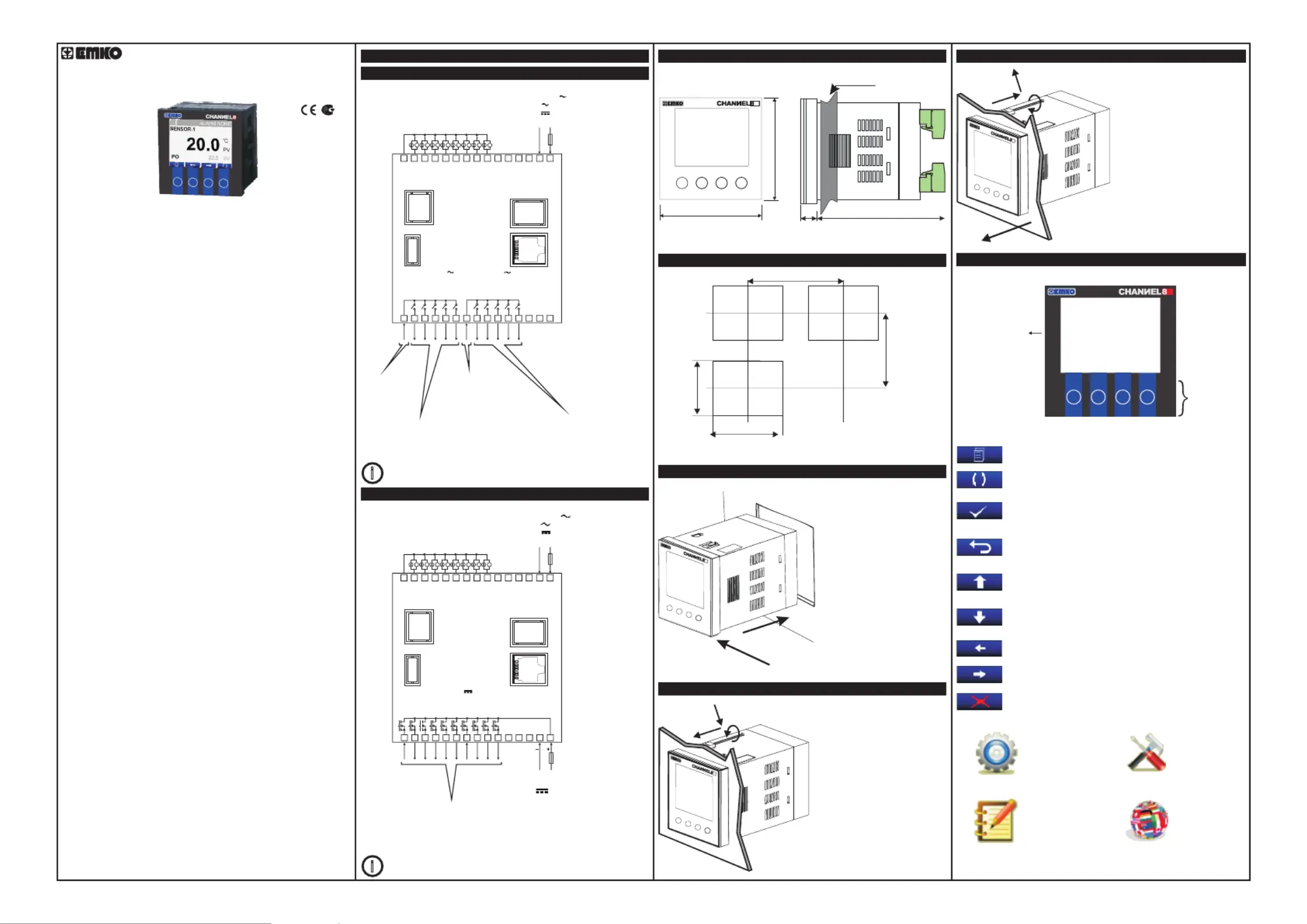
CHANNEL8A-N
8CHANNEL ANALOGSCANNER
96x96DIN1/4
12±1mm/0.47inch
84mm/3.31inch
15 0.59inchmm/
92mm/3.62inch
92mm/3.62inch
129mm/5.08inch(min)
129mm/5.08inch(min)
320x240Pixel
TFT LCD
Standart
Function
Buttons
MENU BUTTON
Used to access Menu page.
ENTER BUTTON
Used to go in to selected page, to make parameter's cell
available tochange and to confirm parameter’s change.
AUTO BUTTON
Used to auto-scan pages.
BACK BUTTON
Used to go back to previous menu and to cancel
parameter's change.
UP BUTTON
Used to go up in menus and lists and also used to increase
parameter's value.
LEFTBUTTON
Usedtogoleftinmenus.
DOWNBUTTON
Usedtogodowninmenusandlistsandalsousedto
decreaseparameter'svalue.
RIGHTBUTTON
Usedtogorightinmenus.
F4
F1 F2 F3
DELETEBUTTON
Usedtoeraselogsonthescreen.
SETTINGS
LOGS
ADVANCE
SETTINGS
LANGUAGE
CHANNEL8A-N8Channel AnalogScanner
-320x240pixelTFTLCDdisplay
-8 Analoginputs
-ON-OFFcontrol
-Relayor(pnp “source”)transistoroutput
-Sensorerrordetection
- Adjustabletemperatureoffset
-3Differentalarmandpre-alarmtypesforeachchannel
(High,LowandBand Alarms)
-Userdefinedchannellabels
-Displayscanmodes
-OperatingwithRealTimeClock(RTC)
-ModBusRTUcommunicationprotocol
(RS-232,RS-485andEthernetcommunication)
-DataLoggingtoUSBFlashMemory
- Adjustabledataloggingtimeinterval
-Passwordprotectionforprogrammingmode
CHANNEL8A-N series 8 channel analog scanner devices are designed
for measuring and logging temperature. They can be used in many
applications with their, alarm outputs, selectable alarm functions, RS-
232 / RS-485 / Ethernet / USB communications.
SPECIFICATIONS
INPUT
AnalogInputs:
Accuracy:
SamplingTime:
OUTPUT
Relay:
DISPLAY
LCDDisplay:
POWERSUPPLY
ENVIRONMENTAL RATINGS
OperatingTemperature:
Humidity:
ProtectionClass:
PHYSICAL SPECIFICATIONS
Weight:
Dimension :
Panel Cut-Out :
0-20mA /4-2mA and0-10VDC Analogue
±0.25%offullscale
400ms
ax.1A@24V
320x240
0...50°C
0-90%RH(nonecondensing)
IP65atfront,IP20atrear
0gr.
96 x 96 mm, Depth:96 mm
92 x 92 mm
W
W
40
Resolution:
InputRessistance:
Transistor:
14Bits
100 for0-20mA inputand
68k for0-10Vinput
ResistiveLoad5A@250V
(ElectricalLife:100.000operation(FullLoad)
PNP(source)typetransistoroutput(M )
pixel TFT LCD
100-240V (-%15/+%10)50/60Hz.7VA
24V (-%15/+%10)50/60Hz.7VA
24V (-%15/+%10)7W
(Itmustbedeterminedinorder.)
V
Z
V
V
Z
ElectricalWiringDiagram
DevicewithRelayOutputs
RS232
COMMUNICATION
5x5A@250V
COMMON-1
COMMON-2
16
21 22
23
24
25 26
27
28 29 30
17
18 19 20
1 2
3
4
5
6
7 8 9 10
11 12
13
14
15
CH-1 ALARM
OUTPUT
CH-
OUTPUT
2 ALARM
CH-
OUTPUT
3 ALARM
CH-
OUTPUT
4 ALARM
CH-
OUTPUT
5 ALARM
CH-
OUTPUT
6 ALARM
CH-
OUTPUT
7 ALARM
CH-
OUTPUT
8 ALARM
GENERAL ALR.
OUTPUT
GENERAL PRE-ALR.
OUTPUT
5x5A@250V
USB2.0
COMMUNICATION
ETHERNET
OR
RS485
COMMUNICATION
CH-1CH-2CH-3CH-4CH-5CH-6CH-7CH-8
100...240V-%15;+%10)50/60Hz7VA
24V(-%15;+%10)50/60Hz7VA
24V(-%15;+%10)7W
L
(+)
N
(-)
DevicewithTransistorOutputs
RS232
COMMUNICATION
1 2
3
4
5
6 7 8 9 10
11 12
13
14
15
USB2.0
COMMUNICATION
ETHERNET
OR
RS485
COMMUNICATION
100...240V(-%15;+%10)50/60Hz7VA
24V(-%15;+%10)50/60Hz7VA
24V(-%15;+%10)7W
L
(+)
N
(-)
i
RS485, Ethernet and USB communications are optional
16
21 22
23
24
25 26
27
28 29 30
17
18 19 20
CH-1 ALARM
OUTPUT
CH-
OUTPUT
2 ALARM
CH-
OUTPUT
3 ALARM
CH-
OUTPUT
4 ALARM
CH-
OUTPUT
5 ALARM
CH-
OUTPUT
6 ALARM
CH-
OUTPUT
7 ALARM
CH-
OUTPUT
8 ALARM
GENERAL ALR.
OUTPUT
GENEAL PRE- ALR.
OUTPUT
10x1A@24V
TRANSISTOROUTPUTS
POWERSUPPLY
24V±%15
i
RS485, Ethernet and USB communications are optional
RelayOutputs
(AlarmOutputsfor
Channels6to8,
General AlarmOutputand
GeneralPre-AlarmOutput)
CH=CHANNEL
PowerSupplyInput
(Itmustbedeterminedinorder.)
Common1
Common2
RelayOutputs
(AlarmOutputsfor
Channels1to5)
PowerSupplyInput
(Itmustbedeterminedinorder.)
TransistorOutputs
(AlarmOutputsfor
Channels1to8,
General AlarmOutputand
GeneralPre-AlarmOutput)
CH=CHANNEL
Maximum
CHANNEL8A-NFrontViewandDimensionsof
PanelCut-Out
1-Before mounting the device
in your panel, make sure that
the cut-out is of the right size.
2-Check front panel gasket
position
3-Insert the device through the
cut-out. If the mounting clamps
are on the unit, put out them
before inserting the unit to the
panel.
PanelMounting
InstallationFixingClamp
The unit is designed for panel
mounting.
1-Insert the unit in the panel
cut-out from the front side.
2- Insert the mounting clamps
to the holes that located top
and bottom sides of device and
screw up the fixing screws until
the unit completely immobile
within the panel.
RemovingfromthePanel
1-Loosen the screws.
2-Pull mounting clamps from
top and bottom fixing sockets.
3-Pull the unit through the
front side of the panel
DefinitionofFrontPanel
AGND
ProcessInputs
(4-20mA /0-20mA)
(0-10V)
ı
+
ı
+
ı
+
ı
+
ı
+
ı
+
ı
+
ı
+
ı
+
ı
+
0-20mA Z
0-10V Z
4-20mA Z
0-20mA Z
0-10V Z
4-20mA Z
0-20mA Z
0-10V Z
4-20mA Z
0-20mA Z
0-10V Z
4-20mA Z
0-20mA Z
0-10VZ
4-20mA Z
0-20mA Z
0-10V Z
4-20mA Z
0-20mA Z
0-10V Z
4-20mA Z
0-20mA Z
0-10V Z
4-20mA Z
AGND
ProcessInputs
(4-20mA /0-20mA)
(0-10V)
ı
+
ı
+
ı
+
ı
+
ı
+
ı
+
ı
+
ı
+
ı
+
ı
+
0-20mA Z
0-10V Z
4-20mA Z
0-20mA Z
0-10V Z
4-20mA Z
0-20mA Z
0-10VZ
4-20mA Z
0-20mA Z
0-10V Z
4-20mA Z
0-20mA Z
0-10VZ
4-20mA Z
0-20mA Z
0-10V Z
4-20mA Z
0-20mA Z
0-10V Z
4-20mA Z
0-20mA Z
0-10V Z
4-20mA Z
CH-1CH-2CH-3CH-4CH-5CH-6CH-7CH-8
96mm/3.78inch
96mm/3.78inch
F1 F2 F3 F4
A
1
2
3
F1 F2 F3 F4
A
1
2
F1 F2 F3 F4
A
F4
F1
F2
F3
A
3
1
2
F1 F2 F3 F4
A

MAINOPERATIONSCREEN
MAINOPERATION(CHANNEL-1SCREEN)
i
i
i
MENUSCREEN
OPERATORPARAMETERS
PASSWORDSCREEN
PressF1orF2directionbuttons
tomovetotheSettingstab.
WhentheF1menubuttonispressed
whilethemainscreenisonthepage,the
menupageisdisplayed.
PARAMETERS
CHANGE
PARAMETERS
CHANGE
OPERATORPARAMETERS
(CHANNEL-1PARAMETERS)
PressF3button.Ifpassword
isdifferentfrom0,password
screenopens.
Enterthepasswordvalueusing
theF1andF2buttons.
Confirmthecharactersoneby
onebypressingF3button.
Onceyouhaveconfirmedthe
lastcharacter,youwillproceed
totheoperatorparameters
screen.
PresstheF1andF2buttonsto
highlightthechannelandpresstheF3
button.
Selecttherelevantparameter
withtheF1andF2buttons.
PresstheF3buttontoselect
theparameter.
UsetheF1andF2buttonstochange
thevalueoftheparameter.
PresstheF3buttontosave
theparametervalue.
DEVICESETTINGS
(Rs485SETTINGS)
DEVICESETTINGS
(USBSETTINGS)
DEVICESETTINGS
(ETHERNETSETTINGS)
DEVICESETTINGS
(DATETIMESETTINGS)
WiththeF1andF2buttonsyoucan
selectandchangetheUSB
parameters.UsetheF3buttonto
save.
WiththeF1andF2buttonsyoucan
selectandchangetheRS485
parameters.UsetheF3buttonto
save.
WiththeF1andF2buttonsyoucan
selectandchangetheETHERNET
parameters.UsetheF3buttonto
save.
WiththeF3buttonyoucanselectthe
Dateand Timeparametersandyou
canchangethevaluewiththeF1,F2
buttons.
i
i
i
ChannelNumber
DeviceFunction
Buttons
Alarm Set
Alarm set value for selected channel is can be adjusted according to this parameter.
It can be adjust between -200 0
O O
C to +65 C.
Pre. Alarm Set
Pre- Alarm set value for selected channel is can be adjusted according to this
parameter. It can be adjust between -200 0
O O
C to +65 C.
i
F4F1
F2
F3
ChannelLabel
PreAlarmStatus
AlarmStatus
ChannelsNames
ProcessValue
F4F1
F2
F3
F4F1
F2
F3
AlarmMessages
ChannelOutput
Status
ChannelNumber
F4F1
F2
F3 F4F1
F2
F3
F4F1
F2
F3 F4F1
F2
F3
F4F1
F2
F3
F4F1
F2
F3
F4F1
F2
F3
F4F1
F2
F3
F4F1
F2
F3F4F1
F2
F3
F4F1
F2
F3
F4F1
F2
F3
F4F1
F2
F3 F4F1
F2
F3
F4F1
F2
F3
F1
F1 F2
F3
F1
F2
F3
F1
F2
F1
F2
F3
F1
F2
OperatorPasswordChange
Passwordfordeviceisadjustedbythisparameter.Operator
DEVICESETTINGS
(PASSWORDCHANGE)
UsetheF1andF2buttonstochange
thevalueoftheparameter.Confirmthe
charactersonebyonebypressingF3
button.
UsetheF1buttontomoveto
the"YES"tabandpresstheF3
button.In1-3secondsthe
devicewillreturntofactory
settings.
F4F1
F2
F3 F4F1
F2
F3
TECHNICIANPARAMETERS
(CONTROL PARAMETERS
TECHNICIANPARAMETERS
PASSWORDSCREEN
TECHNICIANPARAMETERS
PASSWORDSCREEN
TECHNICIANPARAMETERS
PASSWORDINPUTSCREEN
PressF1orF2directionbuttons
tomovetothe Advanced
Settingstab.
PARAMETERS
CHANGE
DEVICESETTINGS
(RS232SETTINGS)
PressF3button.Ifpassword
isdifferentfrom0,password
screenopens.
Enterthepasswordvalueusing
theF1andF2buttons.
Confirmthecharactersoneby
onebypressingF3button.
Onceyouhaveconfirmedthe
lastcharacter,youwillproceed
totheoperatorparameters
UsetheF1andF2buttonstoscrollto
theControlparametersandpressthe
F3button.
SelecttherelevantchannelwiththeF1
andF2buttons.
PresstheF3buttontoselect
theparameter.
UsetheF1andF2buttonstochange
thevalueoftheparameter.Pressthe
F3buttontosavetheparametervalue.
WiththeF1andF2buttonsyou
canselectandchangetheRS232
parameters.UsetheF3buttonto
save.
F4F1
F2
F3 F4F1
F2
F3
F4F1
F2
F3 F4F1
F2
F3
F4F1
F2
F3
F4F1
F2
F3
F4F1
F2
F3
F4F1
F2
F3
F4F1
F2
F3F4F1
F2
F3
F1
F1 F2
F3
F1
F2
F3
F1
F2
F1
F2
F3
F3
F3
F3
F3
TECHNICIANPARAMETERS
(CHANNEL-1)
TECHNICIANPARAMETERS
(CHANNEL-1PARAMETERS)
MainOperationScreensDefinetion AccessingtotheOperatorParameterPages
IfthedisplaytypeparametervalueScreenType=MULTIPLE
If the display scan parameter value Screen Change = ENABLE, each main
operation screen is showing on LCD screen during time defined by Change
Time parameter value.
IfthedisplaytypeparametervalueScreenType=SINGLE
ChannelName
ProcessValue
MAINOPERATION(CHANNEL-4SCREEN)
Pressnumber
F2orF3
buttonsfor
accessingthe
relevantchannel
screen.
If the display scan parameter value Screen Change = ENABLE, each main
operation screen is showing on LCD screen during time defined by Change
Time(sec) parameter value
If more than one alarm messages is present, each alarm message is
showing on LCD screen during 1 second.
MAINOPERATIONSCREEN
OPERATORPARAMETERS
PASSWORDSCREEN
OPERATORPARAMETERS
PASSWORDINPUTSCREEN
OPERATORPARAMETERS
(CHANNEL-1)
OPERATORPARAMETERS
(CHANNEL-1PARAMETERS)
AccessingtotheTechnicianParameterPages
OperatorPagesParametersDefinetions
If no operation is performed for 20 seconds in operator parameters section,
device turns to main operation screen automatically.
If the device has a optional RS485 communication then RS 485 page is
observed, If the device has a optional USB communication then USB page is
observed.
If no operation is performed for 20 seconds in operator or technician
parameters section, device turns to main operation screen automatically.
If the device has a optional ETHERNET communication then ETHERNET
page is observed, otherwise this page is not observed.
MAINOPERATIONSCREEN
MENUSCREEN
WhentheF1menubuttonispressed
whilethemainscreenisonthepage,the
menupageisdisplayed.
DEVICESETTINGS
(DEFAULTSETTINGS)
A
A
A
A
A
A
A
A
A
A
A
A
A
A
A
A
A
A
A
A
A
A
A
A
A
A
A
A
A
A
UnitSelect
Type of unit value is adjusted according to this parameter for selected channel which is
shown on display.The value of parameter C, Bar, Ph, %, mm, m.
O

Hysteresis
Hysteresis parameter value for Alarm and Pre-Alarm is can be adjusted by this
parameter. It can be adjust between -400 0
O O
C to +40 C.
Band Alarm
Bandwith for Band alarm is can be adjusted by this parameter value.
It can be adjust between -400 0
O O
C to +40 C.
Sensor Alarm
Sensor break alarm for selected channel is can be disable or enable by this parameter.
It can be adjust between 0 to 1. Parameter values;
0 = DISABLE
1 = ENABLE
Offset
Process offset value for selected channel is can be adjusted by this parameter.
It can be adjust between -50.0 0
O O
C to +50. C.
ControlParameters-OtherParameters
Screen Type
Main operation screen type is adjusted by this parameter.
It can be adjust between 0 to 1. Parameter values;
0 = MULTIPLE
1 = SINGLE
Screen Change
It can be adjust between 0 to 1. Parameter values;
0 = DISABLE
1 = ENABLE
Display channel scanner mode is adjusted by this parameter.
Change Time(sec)
Display scan period is adjusted by this parameter. All main operation screen is
displayed during time defined by this parameter. It can be adjust between 1 to 3600
secs.
Baudrate
It can be adjust between 0 to 5. Parameter values;
0 = 4800 3 = 38400
1 = 9600 4 = 57600
2 = 19200 5 = 115200
Modbus communication baudrate for RS232 is can be adjusted by this parameter.
Parity
It can be adjust between 0 to 2. Parameter values;
0 = NONE
1 = ODD
2 = EVEN
Modbus communication parity bit for RS232 is can be adjusted by this parameter.
Stop Bit
It can be adjust between 1 to 2. Parameter values;
1 = 1 Stop bit
2 = 2 Stop bits
Modbus communication stop bit for RS232 is can be adjusted by this parameter.
Id
Modbus communication device ID for RS232 is can be adjusted by this parameter.
This parameter value is can be adjusted from 1 to 247.
File Name
USB file name for recording analogue values is can be adjusted by this parameter. File
name can be adjusted maximum 10 characters. Recording file on usb is csv format“ ”
and all data is seperated each other with tab. Example file format is explained below.
Label
When the analogue values are recorded on USB file, user can be defined label for this
recording. Label can be adjusted maximum 10 characters. Label are recorded at the
end of every lines of file.
Date Record
It can be adjust between 0 to 1. Parameter values;
0 = DISABLE
1 = ENABLE
When the analogue values are recorded on USB file, user can be save the recording
time on the file. Recording time is recorded at the beginning of every lines of file.
Record Time(sec)
It can be adjust between 0 to 3600 secs.
Record time interval is can be adjusted by this parameter. Analogue values are
recorded on USB file with this time interval. If
this parameter value is 0 usb recording is disabled.
Flash Memory “USB Flash Memory Stick Detected Test”
Detection of the USB memory device being inserted is tested with this parameter.
When the USB memory device is plugged in, the message "OK" is displayed.
DHCP
It can be adjust between 0 to 1. Parameter Values;
0 = DHCP DISABLE
1 = DHCP ENABLE
DHCP is an automatic configuration protocol used on IP networks, If DHCP is enable,
device is adjust our ethernet communication configuration parameters (IP,
Netmask,Gateway) dynamicaly for your network system. If DHCP is disable, you must
adjust ethernet configuration parameters (IP, Netmask,Gateway) for your network
system.
Port No
Ethernet port number is can be adjusted by this parameter.
Netmask
Subnet mask for ethernet communication is can be adjusted by this parameter. If
DHCP is selected as a enable there is no need to adjust to this parameter, if DHCP is
selected as a disable then user must adjust this parameter according to the their own
network system.
Gateway
Gateway for ethernet communication is can be adjusted by this parameter. If DHCP is
selected as a enable there is no need to adjust to this parameter, if DHCP is selected as
a disable then user must adjust this parameter according to the their own network
system.
Ip No
IP address for ethernet communication is can be adjusted by this parameter. If DHCP
is selected as a enable there is no need to adjust to this parameter, if DHCP is selected
as a disable then user must adjust this parameter.
Channel Status
It can be adjust between 0 to 1. If parameter value
0 = DISABLE
1 = ENABLE
Channel is enabled and disabled by this parameter. If channel is selected as a disabled
this channel is can not be observed in main operation scren for single view mode,
channel alarm is not be controlled and analogue value for this channel is can not be
recording on USB file. ,
Channel Name “ ”Channels label definition
All channels have their own label, is displayed in main operation screen. channel labels is can
be adjusted by this parameter. Channel labels are can be adjusted maximum 10 characters.
Alarm Type
Alarm type for selected channel is can be adjusted according to this parameter.
It can be adjust between 0 to 2. Parameter values;
0 = LOW 1 = HIGH 2 = BAND
PreAlarm Type
Pre-Alarm type for selected channel is can be adjusted according to this parameter.
It can be adjust between 0 to 2. Parameter values;
0 = LOW 1 = HIGH 2 = BAND
BackLightOnLevel
Display backlight is can be controlled by this parameter value. It can be adjust
between 50 to 100.
BackLightOffLevel
CO mode for backlight; in case off selection no backlight . ThisE parameter is can be
adjusted from 1 to 100.
BackLightOffTime
Time for the access to ecomomic backlight mode. This parameter is can be adjusted
from 10 to 300.
DeviceSettings-RS-232Settings
DeviceSettings-RS-485Settings
Baudrate
It can be adjust between 0 to 5. Parameter values;
0 = 4800
1 = 9600
2 = 19200
3 = 38400
4 = 57600
5 = 115200
Modbus communication baudrate for RS485 is can be adjusted by this parameter.
Parity
It can be adjust between 0 to 2. Parameter values;
0 = NONE
1 = ODD
2 = EVEN
Modbus communication parity bit for Rs485 is can be adjusted by this parameter.
Stop Bit
It can be adjust between 1 to 2. Parameter values;
1 = 1 Stop bit
2 = 2 Stop bits
Modbus communication stop bit for Rs485 is can be adjusted by this parameter.
Id
Modbus communication device ID for Rs485 is can be adjusted by this parameter.
This parameter value is can be adjusted from 1 to 247.
DeviceSettings-USBSettings
DeviceSettings-ETHERNETSettings
TcpIp Selection
It can be adjust between 0 to 1.
0 = Modbus RTU Over TCP/IP
1 = Modbus RTU TCP/IP
TCP/IPProtocol is can be adjusted by this parameter.
DeviceSettings-DefaultSettings
Thissectionisusedtoreturndefaultsettingsback.
DeviceSettings-DateandTimeSettings
Date andTime for device is adjusted by this parameter.
DeviceSettings-PasswordChange
Technician Password for device is adjusted by this parameter.
DeviceSettings-SoftwareUpdate
It allows you to update the device's software with a USB flash memory.
Logs
In this page, events logs are shown.
LanguageSelection
Inthispage,thelanguageisselectedforthedevice.
F4F1
F2
F3
F4F1
F2
F3
SET
HYS
BAND
=
=
=
Alarm or Pre-Alarm Set value
Hysteresis value forAlarm and Pre-Alarm output
Bandwidth for BandAlarm.
ON
OFF
Process Value
ON
OFF
Alarm
Output
Process Value
Alarm
Output
SET
HYS
SET
HYS
ON
OFF
Alarm
Output
Process Value
BandAlarm
LowAlarm
HighAlarm
OperationGraphicsof AlarmandPre-AlarmTypes
i
Modbus Addresses
OutputStatus Addresses
OutputsStatus Addresses
Unit
CH-1 ALARMOUT
Channel-1 AlarmOutputStatus
Address
00001
-
CH-2 ALARMOUT
Channel-2 AlarmOutputStatus
00002
-
CH-3 ALARMOUT
Channel-3 AlarmOutputStatus
00003
-
CH-4 ALARMOUT
Channel-4 AlarmOutputStatus
00004
-
CH-5 ALARMOUT
Channel-5 AlarmOutputStatus
00005
-
CH-6 ALARMOUT
Channel-6 AlarmOutputStatus
00006
-
CH-7 ALARMOUT
Channel-7 AlarmOutputStatus
00007
-
CH-8 ALARMOUT
Channel-8 AlarmOutputStatus
00008
-
GEN. ALR.OUT
General AlarmOutputStatus
00009
-
GEN.PRE.ALR.OUT
GeneralPre-alarmOutputStatus
00010
-
Note-1: Outputs status are can be readed with modbus function-1 (read coils).
Device s response for modbus function-1 is always 2 byte data although the modbus’
function request less than 9 outputs port.
ProcessValues Addresses
Unit
CH-1P.VALUE
Channel-1ProcessValue
Address
30001
CH-2P.VALUE
Channel-2ProcessValue
30002
CH-3P.VALUE
Channel-3ProcessValue
30003
CH-4P.VALUE
Channel-4ProcessValue
30004
CH-5P.VALUE
Channel-5ProcessValue
30005
CH-6P.VALUE
Channel-6ProcessValue
30006
CH-7P.VALUE
Channel-7ProcessValue
30007
CH-8P.VALUE
Channel-8ProcessValue
30008
Note-2: Process values are can be readed with modbus function-4 (read input
register). Because of the process values are displayed on LCD screen with point, the
reading valuesfrom modbus is 10 times than the real values.
ParametersModbus Addresses
ParameterValues Addresses
Unit
CH-1NAME
Channel-1Name
Address
42000-42004
CH-2NAME
Channel-2Name
42005-42009
String
42005-42009
CH-3NAME
Channel-3Name
42010-42014
CH-4NAME
Channel-4Name
42015-42019
CH-5NAME
Channel-5Name
42020-42024
CH-6NAME
Channel-6Name
42025-42029
CH-7NAME
Channel-7Name
42030-42034
CH-8NAME
Channel-8Name
42035-42039
String
String
String
String
String
String
String
FILENAME
USBFileName
42040-42044
String
LABEL
USBLabel
42045-42049
String
CH-1 ALARMSET
Channel-1 AlarmSetValue
42050
CH-1PRE A.SET
Channel-1PrealarmSetValue
42051
CH-1HYSTERESIS
Channel-1HysteresisValue
42052
CH-1BAND ALARM
Channel-1BandwithValue
42053
CH-2 ALARMSET
Channel-2 AlarmSetValue
42054
CH-2PRE A.SET
Channel-2PrealarmSetValue
42055
CH-2HYSTERESIS
Channel-2HysteresisValue
42056
CH-2BAND ALARM
Channel-2BandwithValue
42057
CH-3 ALARMSET
Channel-3 AlarmSetValue
42058
CH-3PRE A.SET
Channel-3PrealarmSetValue
42059
CH-3HYSTERESIS
Channel-3HysteresisValue
42060
CH-3BAND ALARM
Channel-3BandwithValue
42061
CH-4 ALARMSET
Channel-4 AlarmSetValue
42062
CH-4PRE A.SET
Channel-4PrealarmSetValue
42063
CH-4HYSTERESIS
Channel-4HysteresisValue
42064
CH-4BAND ALARM
Channel-4BandwithValue
42065
CH-5 ALARMSET
Channel-5 AlarmSetValue
42066
CH-5PRE A.SET
Channel-5PrealarmSetValue
42067
CH-5HYSTERESIS
Channel-5HysteresisValue
42068
CH-5BAND ALARM
Channel-5BandwithValue
42069
CH-6 ALARMSET
Channel-6 AlarmSetValue
42070
CH-6PRE A.SET
Channel-6PrealarmSetValue
42071
CH-6HYSTERESIS
Channel-6HysteresisValue
42072
CH-6BAND ALARM
Channel-6BandwithValue
42073
CH-7 ALARMSET
Channel-7 AlarmSetValue
42074
CH-7PRE A.SET
Channel-7PrealarmSetValue
42075
CH-7HYSTERESIS
Channel-7HysteresisValue
42076
CH-7BAND ALARM
Channel-7BandwithValue
42077
*
()
*
()
*
()
*
()
*
()
*
()
*
()
*
()
*
()
*
()
*
()
*
()
*
()
*
()
*
()
*
()
*
()
*
()
*
()
*
()
*
()
*
()
*
()
*
()
*
()
*
()
*
()
*
()
SET
(SET -(BAND/2)) (SET +(BAND/2))
HYS HYS
TechnicianParameters
TechnicianPagesParametersDefinetions
USB Recording File Example
2011-06-23-17:26:09130.6129.1130.5129.5130.0129.9130.3129.1SAMPLE
2011-06-23-17:26:10130.6129.1130.5129.5130.0129.9130.3129.1SAMPLE
2011-06-23-17:26:12130.6129.1130.5129.5130.0129.9130.3129.1SAMPLE
2011-06-23-17:26:13130.6129.1130.5129.5130.0129.9130.3129.1SAMPLE
Recording Time CH-1
Value
CH
Value
-2 CH
Value
-3 CH
Value
-4 CH
Value
-5 CH
Value
-6 CH
Value
-7 CH
Value
-8 Label
Calib. Low
Calibration Low value for selected channel can be adjusted according to this
parameter.
Calib. High
Calibration High value for selected channel can be adjusted according to this
parameter.
Sensor Type
Analogue input signal to be applied according to this parameter for selected channel
which is shown on Display.
0 = 4-20 mA 1 = 0-20 mA 2 = 0-10 V
A
A
O
C/Ph/Bar
O
C/Ph/Bar
O
C/Ph/Bar
O
C/Ph/Bar
O
C/Ph/Bar
O
C/Ph/Bar
O
C/Ph/Bar
O
C/Ph/Bar
O
C/Ph/Bar
O
C/Ph/Bar
O
C/Ph/Bar
O
C/Ph/Bar
O
C/Ph/Bar
O
C/Ph/Bar
O
C/Ph/Bar
O
C/Ph/Bar
O
C/Ph/Bar
O
C/Ph/Bar
O
C/Ph/Bar
O
C/Ph/Bar
O
C/Ph/Bar
O
C/Ph/Bar
O
C/Ph/Bar
O
C/Ph/Bar
O
C/Ph/Bar
O
C/Ph/Bar
O
C/Ph/Bar
O
C/Ph/Bar
O
C/Ph/Bar
O
C/Ph/Bar
O
C/Ph/Bar
O
C/Ph/Bar
O
C/Ph/Bar
O
C/Ph/Bar
O
C/Ph/Bar
O
C/Ph/Bar
Internal Recording
The device can record in memory. When a USB memory is inserted, the recordings are
transferred to the USB memory with the file name containing the current date and
time.(Exp: 2017-07-30-09-08-12-CHAN8.txt) icon and transaction status (%)
are displayed on the screen until the transfer is complete.
If you want to eject the USB memory during transfer or recording; Press the F4 button
for 5 seconds and the USB memory must be removed (within 5 seconds) before the
icon on the screen disappears. If the USB stick is not removed during this time, the
transfer will resume from where it left off.
The device can store up to (Record time x 2) daily memos in its memory.Not:
Produktspecifikationer
Varumärke: | Emko |
Kategori: | Temperaturregulator |
Modell: | CHANNEL8A-N |
Behöver du hjälp?
Om du behöver hjälp med Emko CHANNEL8A-N ställ en fråga nedan och andra användare kommer att svara dig
Temperaturregulator Emko Manualer
19 September 2024
19 September 2024
19 September 2024
19 September 2024
16 September 2024
16 September 2024
16 September 2024
16 September 2024
16 September 2024
7 September 2024
Temperaturregulator Manualer
- AEG
- Dimplex
- Ventus
- Techno Line
- Wachendorff
- Voltcraft
- Berker
- Kathrein
- Carel
- SRS
- Bulex
- Fluke
- Jung
- Ziehl
- Cocraft
Nyaste Temperaturregulator Manualer
28 December 2024
28 December 2024
28 December 2024
28 December 2024
28 December 2024
28 December 2024
28 December 2024
28 December 2024
28 December 2024
17 December 2024