Emko CHANNEL8N Bruksanvisning
Läs gratis den bruksanvisning för Emko CHANNEL8N (4 sidor) i kategorin Termostat. Guiden har ansetts hjälpsam av 32 personer och har ett genomsnittsbetyg på 4.6 stjärnor baserat på 16.5 recensioner. Har du en fråga om Emko CHANNEL8N eller vill du ställa frågor till andra användare av produkten? Ställ en fråga
Sida 1/4

ENG CHANNEL8N 01 V00 03/17
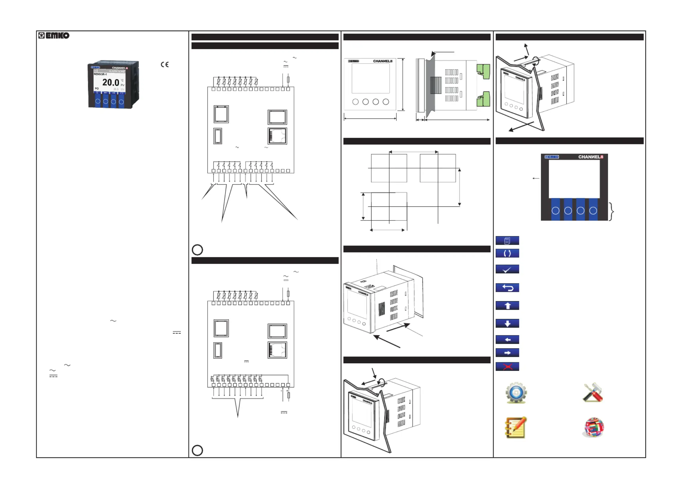
CHANNEL8N
8 CHANNEL PT-100 SCANNER
96 x 96 DIN 1/4
96 mm / 3.78 inch
96 mm / 3.78 inch
12 ± 1 mm / 0.47 inch
84 mm / 3.31 inch
15 0.59 inchmm /
92mm/3.62 inch
92mm/3.62 inch
129mm/5.08 inch(min)
320 x 240 Pixel
TFT LCD
Standart
Function
Buttons
MENU BUTTON
Used to access Menu page.
ENTER BUTTON
Used to go in to selected page, to make parameter's cell
available to change and to confirm parameter’s change.
AUTO BUTTON
Used to auto-scan pages.
BACK BUTTON
Used to go back to previous menu and to cancel
parameter's change.
UP BUTTON
Used to go up in menus and lists and also used to increase
parameter's value.
LEFT BUTTON
Used to go left in menus.
F1 F2 F3 F4
F4F1
F2
F3
DOWN BUTTON
Used to go downin menus and lists and also used to
decrease parameter's value.
RIGHT BUTTON
Used to go right in menus.
F4
1F F2 3F
DELETE BUTTON
Used to erase logs on the screen.
SETTINGS
LOGS
ADVANCE
SETTINGS
LANGUAGE
CHANNEL8N 8 Channel PT-100 Scanner
- 320 x 240 pixel TFT LCD display
- 8 PT-100 temperature sensor inputs
- ON-OFF control
- Relay or (pnp “source”) transistor output
- Sensor error detection
- Adjustable temperature offset
- 3 Different alarm and pre-alarm types for each channel
(High, Low and Band Alarms)
- User defined channel labels
- Display scan modes
- Operating with Real Time Clock (RTC)
- ModBus RTU communication protocol
(RS-232, RS-485 and Ethernet communication)
- Data Logging to USB Flash Memory
- Adjustable data logging time interval
- Password protection for programming mode
CHANNEL8N series 8 channel PT100 scanner devices are designed for
measuring and logging temperature. They can be used in many
applications with their PT-100 process input, alarm outputs, selectable
alarm functions, RS-232 / RS-485 / Ethernet / USB communications.
SPECIFICATIONS
INPUT
Thermoresistance(RTD) : 2 wire PT100 (IEC 751) (ITS90)
Measurement Range : -200°C / +650°C
Accuracy : ± 0.25% of full scale
Sensor Break Protection : Upscale
W
OUTPUT
Relay :
ax. 1A@24V
DISPLAY
LCD Display : 320x240
POWER SUPPLY
ENVIRONMENTAL RATINGS
Operating Temperature : 0...50°C
Humidity : 0-90%RH (none condensing)
Protection Class : IP65 at front, IP20 at rear
PHYSICAL SPECIFICATIONS
Weight : 400 gr.
Dimension : 96 x 96 mm, Depth:96 mm
Panel Cut-Out : 92 x 92 mm
Sampling Time : 400msecs.
Line Compensation : Maximum 10
Input Ressistance : > 10MW
Resistive Load 5A@250V
(Electrical Life : 100.000 operation (Full Load)
Transistor : PNP(source) type transistor output (M )
pixel TFT LCD
100 - 240 V (-%15 / +%10) 50/60 Hz. 7VA
24 V (-%15 / +%10) 50/60 Hz. 7VA
24 V (-%15 / +%10) 7W
(It must be determined in order.)
Electrical Wiring Diagram
Device with Relay Outputs
RS 232
COMMUNICATION
5 x 5A@250V
COMMON-1
COMMON-2
16
21 22
23
24
25 26
27
28 29
30
17
18 19
20
1 2
3
4
5
6
7
8 9
10
11 12
13
14
15
CH-1 ALARM
OUTPUT
CH-2 ALARM
OUTPUT
CH-3 ALARM
OUTPUT
CH-4 ALARM
OUTPUT
CH-5 ALARM
OUTPUT
CH-6 ALARM
OUTPUT
CH-7 ALARM
OUTPUT
CH-8 ALARM
OUTPUT
GENERAL ALR.
OUTPUT
GENERAL PRE-ALR.
OUTPUT
5 x 5A@250V
USB 2.0
COMMUNICATION
ETHERNET
OR
RS485
COMMUNICATION
PT-100
CH-1
PT-100
PT-100
PT-100
PT-100
PT-100
PT-100
PT-100
CH-2CH-3CH-4CH-5CH-6CH-7CH-8
AGND
100...240V - %15;+%10) 50/60Hz 7VA
24V (-%15;+%10) 50/60Hz 7VA
24V (-%15;+%10) 7W
L
(+)
N
(-)
Device with Transistor Outputs
RS 232
COMMUNICATION
1 2
3
4
5
6
7
8 9
10
11 12
13
14
15
USB 2.0
COMMUNICATION
ETHERNET
OR
RS485
COMMUNICATION
PT-100
CH-1
PT-100
PT-100
PT-100
PT-100
PT-100
PT-100
PT-100
CH-2CH-3CH-4CH-5CH-6CH-7CH-8
AGND
100...240V (- %15;+%10) 50/60Hz 7VA
24V (-%15;+%10) 50/60Hz 7VA
24V (-%15;+%10) 7W
L
(+)
N
(-)
i
i
i
i
i
RS485, Ethernet and USB communications are optional
16
21 22
23
24
25 26
27
28 29
30
17
18 19
20
CH-1 ALARM
OUTPUT
CH-2 ALARM
OUTPUT
CH-3 ALARM
OUTPUT
CH-4 ALARM
OUTPUT
CH-5 ALARM
OUTPUT
CH-6 ALARM
OUTPUT
CH-7 ALARM
OUTPUT
CH-8 ALARM
OUTPUT
GENERAL ALR.
OUTPUT
GENEAL PRE- ALR.
OUTPUT
10 x 1A@24V
TRANSISTOR OUTPUTS
POWER SUPPLY
24V ±%15
i
i
i
i
i
RS485, Ethernet and USB communications are optional
Relay Outputs
(Alarm Outputs for
Channels 6 to 8,
General Alarm Output and
General Pre-Alarm Output )
CH = CHANNEL
Power Supply Input
(It must be determined in order.)
Process Inputs
(PT-100)
Common1
Common2
Relay Outputs
(Alarm Outputs for
Channels 1 to 5)
Power Supply Input
(It must be determined in order.)
Process Inputs
(PT-100)
Transistor Outputs
(Alarm Outputs for
Channels 1 to 8,
General Alarm Output and
General Pre-Alarm Output )
CH = CHANNEL
Maximum
CHANNEL8N Front View and Dimensions of
Panel Cut-Out
1-Before mounting the device
in your panel, make sure that
the cut-out is of the right size.
2-Check front panel gasket
position
3-Insert the device through the
cut-out. If the mounting clamps
are on the unit, put out them
before inserting the unit to the
panel.
Panel Mounting
Installation Fixing Clamp
The unit is designed for panel
mounting.
1-Insert the unit in the panel
cut-out from the front side.
2- Insert the mounting clamps
to the holes that located top
and bottom sides of device and
screw up the fixing screws until
the unit completely immobile
within the panel.
1
2
3
F1 F2 F3 F4
1
2
F1 F2 F3 4F
Removing from the Panel
1-Loosen the screws.
2-Pull mounting clamps from
top and bottom fixing sockets.
3-Pull the unit through the
front side of the panel
Definition of Front Panel
3
1
2
F1 F2 F3 4
F

MAIN OPERATION SCREEN
MAIN OPERATION (CHANNEL-1 SCREEN)
i
i
i
i
i
i
i
i
i
i
i
i
i
i
i
MENU SCREEN
OPERATOR PARAMETERS
PASSWORD SCREEN
Press F1 or F2 direction buttons
to move to the Settings tab.
When the F1 menu button is pressed
while the main screen is on the page, the
menu page is displayed.
PARAMETERS
CHANGE
PARAMETERS
CHANGE
OPERATOR PARAMETERS
(CHANNEL-1 PARAMETERS)
Press F3 button. If password
is different from 0, password
screen opens.
Enter the password value using
the F1 and F2 buttons.
Confirm the characters one by
one by pressing F3 button.
Once you have confirmed the
last character, you will proceed
to the operator parameters
screen.
Press the F1 and F2 buttons to
highlight the channel and press the F3
button.
Select the relevant parameter
with the F1 and F2 buttons.
Press the F3 button to select
the parameter.
Use the F1 and F2 buttons to change
the value of the parameter.
Press the F3 button to save
the parameter value.
DEVICE SETTINGS
(Rs485 SETTINGS)
DEVICE SETTINGS
(USB SETTINGS)
DEVICE SETTINGS
(ETHERNET SETTINGS)
DEVICE SETTINGS
(DATE TIME SETTINGS)
With the F1 and F2 buttons you can
select and change the USB
parameters. Use the F3 button to
save.
With the F1 and F2 buttons you can
select and change the RS485
parameters. Use the F3 button to
save.
With the F1 and F2 buttons you can
select and change the ETHERNET
parameters. Use the F3 button to
save.
With the F3 button you can select the
Date and Time parameters and you
can change the value with the F1, F2
buttons.
i
i
i
i
i
i
i
i
i
i
i
i
i
i
i
Channel Number
Device Function
Buttons
Alarm Set
Alarm set value for selected channel is can be adjusted according to this parameter.
It can be adjust between -200 0
O O
C to +65 C.
Pre. Alarm Set
Pre- Alarm set value for selected channel is can be adjusted according to this
parameter. It can be adjust between -200 0
O O
C to +65 C.
i
i
i
i
i
F4F1
F2
F3
Channel Label
PreAlarm Status
Alarm Status
Channels Names
Process Value
F4F1
F2
F3
F4F1
F2
F3
Alarm Messages
Channel Output
Status
Channel Number
F4F1
F2
F3 F4F1
F2
F3
F4F1
F2
F3 F4F1
F2
F3
F4F1
F2
F3
F4F1
F2
F3
F4F1
F2
F3
F4F1
F2
F3
F4F1
F2
F3F4F1
F2
F3
F4F1
F2
F3
F4F1
F2
F3
F4F1
F2
F3 F4F1
F2
F3
F4F1
F2
F3
F1
F1 F2
F3
F1
F2
F3
F1
F2
F1
F2
F3
F1
F2
Operator Password Change
Password for device is adjusted by this parameter.Operator
DEVICE SETTINGS
(PASSWORD CHANGE)
Use the F1 and F2 buttons to change
the value of the parameter. Confirm the
characters one by one by pressing F3
button.
Use the F1 button to move to
the "YES" tab and press the F3
button. In 1-3 seconds the
device will return to factory
settings.
F4F1
F2
F3 F4F1
F2
F3
TECHNICIAN PARAMETERS
(CONTROL PARAMETERS
TECHNICIAN PARAMETERS
PASSWORD SCREEN
TECHNICIAN PARAMETERS
PASSWORD SCREEN
TECHNICIAN PARAMETERS
PASSWORD INPUT SCREEN
Press F1 or F2 direction buttons
to move to the Advanced
Settings tab.
PARAMETERS
CHANGE
DEVICE SETTINGS
(RS232 SETTINGS)
Press F3 button. If password
is different from 0, password
screen opens.
Enter the password value using
the F1 and F2 buttons.
Confirm the characters one by
one by pressing F3 button.
Once you have confirmed the
last character, you will proceed
to the operator parameters
Use the F1 and F2 buttons to scroll to
the Control parameters and press the
F3 button.
Select the relevant channel with the F1
and F2 buttons.
Press the F3 button to select
the parameter.
Use the F1 and F2 buttons to change
the value of the parameter. Press the
F3 button to save the parameter value.
With the F1 and F2 buttons you
can select and change the RS232
parameters. Use the F3 button to
save.
F4F1
F2
F3 F4F1
F2
F3
F4F1
F2
F3 F4F1
F2
F3
F4F1
F2
F3
F4F1
F2
F3
F4F1
F2
F3
F4F1
F2
F3
F4F1
F2
F3F4F1
F2
F3
F1
F1 F2
F3
F1
F2
F3
F1
F2
F1
F2
F3
F3
F3
F3
F3
TECHNICIAN PARAMETERS
(CHANNEL-1)
TECHNICIAN PARAMETERS
(CHANNEL-1 PARAMETERS)
Main Operation Screens Definetion Accessing to the Operator Parameter Pages
If the display type parameter value Screen Type = MULTIPLE
If the display scan parameter value Screen Change = ENABLE, each main
operation screen is showing on LCD screen during time defined by Change
Time parameter value.
If the display type parameter value Screen Type = SINGLE
Channel Name
Process Value
MAIN OPERATION (CHANNEL-4 SCREEN)
Press number
F2 or F3
buttons for
accessing the
relevant channel
screen.
If the display scan parameter value Screen Change = ENABLE, each main
operation screen is showing on LCD screen during time defined by Change
Time(sec) parameter value
If more than one alarm messages is present, each alarm message is
showing on LCD screen during 1 second.
MAIN OPERATION SCREEN
OPERATOR PARAMETERS
PASSWORD SCREEN
OPERATOR PARAMETERS
PASSWORD INPUT SCREEN
OPERATOR PARAMETERS
(CHANNEL-1)
OPERATOR PARAMETERS
(CHANNEL-1 PARAMETERS)
Accessing to the Technician Parameter Pages
Operator Pages Parameters Definetions
If no operation is performed for 20 seconds in operator parameters section,
device turns to main operation screen automatically.
If the device has a optional RS485 communication then RS 485 page is
observed, If the device has a optional USB communication then USB page is
observed.
If no operation is performed for 20 seconds in operator or technician
parameters section, device turns to main operation screen automatically.
If the device has a optional ETHERNET communication then ETHERNET
page is observed, otherwise this page is not observed.
MAIN OPERATION SCREEN
MENU SCREEN
When the F1 menu button is pressed
while the main screen is on the page, the
menu page is displayed.
DEVICE SETTINGS
(DEFAULT SETTINGS)

Hysteresis
Hysteresis parameter value for Alarm and Pre-Alarm is can be adjusted by this
parameter. It can be adjust between -400 0
O O
C to +40 C.
Band Alarm
Bandwith for Band alarm is can be adjusted by this parameter value.
It can be adjust between -400 0
O O
C to +40 C.
Sensor Alarm
Sensor break alarm for selected channel is can be disable or enable by this parameter.
It can be adjust between 0 to 1. Parameter values;
0 = DISABLE
1 = ENABLE
Offset
Process offset value for selected channel is can be adjusted by this parameter.
It can be adjust between -50.0 0
O O
C to +50. C.
Control Parameters- Other Parameters
Screen Type
Main operation screen type is adjusted by this parameter.
It can be adjust between 0 to 1. Parameter values;
0 = MULTIPLE
1 = SINGLE
Screen Change
It can be adjust between 0 to 1. Parameter values;
0 = DISABLE
1 = ENABLE
Display channel scanner mode is adjusted by this parameter.
Change Time(sec)
Display scan period is adjusted by this parameter. All main operation screen is
displayed during time defined by this parameter. It can be adjust between 1 to 3600
secs.
Baudrate
It can be adjust between 0 to 5. Parameter values;
0 = 4800
1 = 9600
2 = 19200
3 = 38400
4 = 57600
5 = 115200
Modbus communication baudrate for RS232 is can be adjusted by this parameter.
Parity
It can be adjust between 0 to 2. Parameter values;
0 = NONE
1 = ODD
2 = EVEN
Modbus communication parity bit for RS232 is can be adjusted by this parameter.
Stop Bit
It can be adjust between 1 to 2. Parameter values;
1 = 1 Stop bit
2 = 2 Stop bits
Modbus communication stop bit for RS232 is can be adjusted by this parameter.
Id
Modbus communication device ID for RS232 is can be adjusted by this parameter.
This parameter value is can be adjusted from 1 to 247.
File Name
USB file name for recording analogue values is can be adjusted by this parameter. File
name can be adjusted maximum 10 characters. Recording file on usb is “csv” format
and all data is seperated each other with tab. Example file format is explained below.
Label
When the analogue values are recorded on USB file, user can be defined label for this
recording. Label can be adjusted maximum 10 characters. Label are recorded at the
end of every lines of file.
Date Record
It can be adjust between 0 to 1. Parameter values;
0 = DISABLE
1 = ENABLE
When the analogue values are recorded on USB file, user can be save the recording
time on the file. Recording time is recorded at the beginning of every lines of file.
Record Time(sec)
It can be adjust between 0 to 3600 secs.
Record time interval is can be adjusted by this parameter. Analogue values are
recorded on USB file with this time interval. If
this parameter value is 0 usb recording is disabled.
Flash Memory “USB Flash Memory Stick Detected Test”
Detection of the USB memory device being inserted is tested with this parameter.
When the USB memory device is plugged in, the message "OK" is displayed.
DHCP
It can be adjust between 0 to 1. Parameter Values;
0 = DHCP DISABLE
1 = DHCP ENABLE
DHCP is an automatic configuration protocol used on IP networks, If DHCP is enable,
device is adjust our ethernet communication configuration parameters (IP,
Netmask,Gateway) dynamicaly for your network system. If DHCP is disable, you must
adjust ethernet configuration parameters (IP, Netmask,Gateway) for your network
system.
Port No
Ethernet port number is can be adjusted by this parameter.
Netmask
Subnet mask for ethernet communication is can be adjusted by this parameter. If
DHCP is selected as a enable there is no need to adjust to this parameter, if DHCP is
selected as a disable then user must adjust this parameter according to the their own
network system.
Gateway
Gateway for ethernet communication is can be adjusted by this parameter. If DHCP is
selected as a enable there is no need to adjust to this parameter, if DHCP is selected as
a disable then user must adjust this parameter according to the their own network
system.
Ip No
IP address for ethernet communication is can be adjusted by this parameter. If DHCP
is selected as a enable there is no need to adjust to this parameter, if DHCP is selected
as a disable then user must adjust this parameter.
Channel Status
It can be adjust between 0 to 1. If parameter value
0 = DISABLE
1 = ENABLE
Channel is enabled and disabled by this parameter. If channel is selected as a disabled
this channel is can not be observed in main operation scren for single view mode,
channel alarm is not be controlled and analogue value for this channel is can not be
recording on USB file. ,
Channel Name “ ” Channels label definition
All channels have their own label, is displayed in main operation screen. channel labels is can
be adjusted by this parameter. Channel labels are can be adjusted maximum 10 characters.
Alarm Type
Alarm type for selected channel is can be adjusted according to this parameter.
It can be adjust between 0 to 2. Parameter values;
0 = LOW
1 = HIGH
2 = BAND
PreAlarm Type
Pre-Alarm type for selected channel is can be adjusted according to this parameter.
It can be adjust between 0 to 2. Parameter values;
0 = LOW
1 = HIGH
2 = BAND
BackLightOnLevel
Display backlight is can be controlled by this parameter value. It can be adjust
between 50 to 100.
BackLightOffLevel
CO mode for backlight; in case off selection no backlight . ThisE parameter is can be
adjusted from 1 to 100.
BackLightOffTime
Time for the access to ecomomic backlight mode. This parameter is can be adjusted
from 10 to 300.
Device Settings - RS-232 Settings
Device Settings - RS-485 Settings
Baudrate
It can be adjust between 0 to 5. Parameter values;
0 = 4800
1 = 9600
2 = 19200
3 = 38400
4 = 57600
5 = 115200
Modbus communication baudrate for RS485 is can be adjusted by this parameter.
Parity
It can be adjust between 0 to 2. Parameter values;
0 = NONE
1 = ODD
2 = EVEN
Modbus communication parity bit for Rs485 is can be adjusted by this parameter.
Stop Bit
It can be adjust between 1 to 2. Parameter values;
1 = 1 Stop bit
2 = 2 Stop bits
Modbus communication stop bit for Rs485 is can be adjusted by this parameter.
Id
Modbus communication device ID for Rs485 is can be adjusted by this parameter.
This parameter value is can be adjusted from 1 to 247.
Device Settings - USB Settings
Device Settings - ETHERNET Settings
TcpIp Selection
It can be adjust between 0 to 1.
0 = Modbus RTU Over TCP/IP
1 = Modbus RTU TCP/IP
TCP/IP Protocol is can be adjusted by this parameter.
Device Settings -Default Settings
This section is used to return default settings back.
Device Settings - Date and Time Settings
Date and Time for device is adjusted by this parameter.
Device Settings - Password Change
Technician Password for device is adjusted by this parameter.
Device Settings - Software Update
It allows you to update the device's software with a USB flash memory.
Logs
In this page, events logs are shown.
Language Selection
In this page, the language is selected for the device.
F4F1
F2
F3
F4F1
F2
F3
SET = Alarm or Pre-Alarm Set value
HYS = Hysteresis value for Alarm and Pre-Alarm output
BAND= Bandwidth for Band Alarm.
ON
OFF
Process Value
ON
OFF
Alarm
Output
Process Value
Alarm
Output
SET
HYS
SET
HYS
ON
OFF
Alarm
Output
Process Value
Band Alarm
Low Alarm
High Alarm
Operation Graphics of Alarm and Pre-Alarm Types
i
i
i
i
i
Modbus Addresses
Output Status Addresses
Outputs Status Addresses
Unit
CH-1 ALARM OUT
Channel-1 Alarm Output Status
Address
00001
-
CH-2 ALARM OUT
Channel-2 Alarm Output Status
00002
-
CH-3 ALARM OUT
Channel-3 Alarm Output Status
00003
-
CH-4 ALARM OUT
Channel-4 Alarm Output Status
00004
-
CH-5 ALARM OUT
Channel-5 Alarm Output Status
00005
-
CH-6 ALARM OUT
Channel-6 Alarm Output Status
00006
-
CH-7 ALARM OUT
Channel-7 Alarm Output Status
00007
-
CH-8 ALARM OUT
Channel-8 Alarm Output Status
00008
-
GEN. ALR. OUT
General Alarm Output Status
00009
-
GEN.PRE.ALR. OUT
General Pre-alarm Output Status
00010
-
Note-1: Outputs status are can be readed with modbus function-1 (read coils).
Device’s response for modbus function-1 is always 2 byte data although the modbus
function request less than 9 outputs port.
Process Values Addresses
Unit
CH-1 P. VALUE
Channel-1 Process Value
Address
30001
O
C
CH-2 P. VALUE
Channel-2 Process Value
30002
CH-3 P. VALUE
Channel-3 Process Value
30003
CH-4 P. VALUE
Channel-4 Process Value
30004
CH-5 P. VALUE
Channel-5 Process Value
30005
CH-6 P. VALUE
Channel-6 Process Value
30006
CH-7 P. VALUE
Channel-7 Process Value
30007
CH-8 P. VALUE
Channel-8 Process Value
30008
Note-2: Process values are can be readed with modbus function-4 (read input
register). Because of the process values are displayed on LCD screen with point, the
reading values from modbus is 10 times than the real values.
O
C
O
C
O
C
O
C
O
C
O
C
O
C
Parameters Modbus Addresses
Parameter Values Addresses
Unit
CH-1 NAME
Channel-1 Name
Address
42000 - 42004
CH-2 NAME
Channel-2 Name
42005 - 42009
String
42005 - 42009
CH-3 NAME
Channel-3 Name
42010 - 42014
CH-4 NAME
Channel-4 Name
42015 - 42019
CH-5 NAME
Channel-5 Name
42020 - 42024
CH-6 NAME
Channel-6 Name
42025 - 42029
CH-7 NAME
Channel-7 Name
42030 - 42034
CH-8 NAME
Channel-8 Name
42035 - 42039
String
String
String
String
String
String
String
FILE NAME
USB File Name
42040 - 42044
String
LABEL
USB Label
42045 - 42049
String
CH-1 ALARM SET
Channel-1 Alarm Set Value
42050
CH-1 PRE A. SET
Channel-1 Prealarm Set Value
42051
CH-1 HYSTERESIS
Channel-1 Hysteresis Value
42052
CH-1 BAND ALARM
Channel-1 Bandwith Value
42053
CH-2 ALARM SET
Channel-2 Alarm Set Value
42054
CH-2 PRE A. SET
Channel-2 Prealarm Set Value
42055
CH-2 HYSTERESIS
Channel-2 Hysteresis Value
42056
CH-2 BAND ALARM
Channel-2 Bandwith Value
42057
CH-3 ALARM SET
Channel-3 Alarm Set Value
42058
CH-3 PRE A. SET
Channel-3 Prealarm Set Value
42059
CH-3 HYSTERESIS
Channel-3 Hysteresis Value
42060
CH-3 BAND ALARM
Channel-3 Bandwith Value
42061
CH-4 ALARM SET
Channel-4 Alarm Set Value
42062
CH-4 PRE A. SET
Channel-4 Prealarm Set Value
42063
CH-4 HYSTERESIS
Channel-4 Hysteresis Value
42064
CH-4 BAND ALARM
Channel-4 Bandwith Value
42065
CH-5 ALARM SET
Channel-5 Alarm Set Value
42066
CH-5 PRE A. SET
Channel-5 Prealarm Set Value
42067
CH-5 HYSTERESIS
Channel-5 Hysteresis Value
42068
CH-5 BAND ALARM
Channel-5 Bandwith Value
42069
CH-6 ALARM SET
Channel-6 Alarm Set Value
42070
CH-6 PRE A. SET
Channel-6 Prealarm Set Value
42071
CH-6 HYSTERESIS
Channel-6 Hysteresis Value
42072
CH-6 BAND ALARM
Channel-6 Bandwith Value
42073
CH-7 ALARM SET
Channel-7 Alarm Set Value
42074
CH-7 PRE A. SET
Channel-7 Prealarm Set Value
42075
CH-7 HYSTERESIS
Channel-7 Hysteresis Value
42076
CH-7 BAND ALARM
Channel-7 Bandwith Value
42077
O
C
O
C
O
C
O
C
O
C
O
C
O
C
O
C
O
C
O
C
O
C
O
C
O
C
O
C
O
C
O
C
O
C
O
C
O
C
O
C
O
C
O
C
O
C
O
C
O
C
O
C
O
C
O
C
*
( )
*
( )
*
( )
*
( )
*
( )
*
( )
*
( )
*
( )
*
( )
*
( )
*
( )
*
( )
*
( )
*
( )
*
( )
*
( )
*
( )
*
( )
*
( )
*
( )
*
( )
*
( )
*
( )
*
( )
*
( )
*
( )
*
( )
*
( )
SET
(SET - (BAND/2)) (SET + (BAND/2))
HYS HYS
Technician Parameters
Technician Pages Parameters Definetions
USB Recording File Example
2011-06-23-17:26:09 130.6 129.1 130.5 129.5 130.0 129.9 130.3 129.1 SAMPLE
2011-06-23-17:26:10 130.6 129.1 130.5 129.5 130.0 129.9 130.3 129.1 SAMPLE
2011-06-23-17:26:12 130.6 129.1 130.5 129.5 130.0 129.9 130.3 129.1 SAMPLE
2011-06-23-17:26:13 130.6 129.1 130.5 129.5 130.0 129.9 130.3 129.1 SAMPLE
Recording Time CH-1
Value
CH-2
Value
CH-3
Value
CH-4
Value
CH-5
Value
CH-6
Value
CH-7
Value
CH-8
Value
Label
Internal Recording
The device can record in memory. When a USB memory is inserted, the recordings are
transferred to the USB memory with the file name containing the current date and
time.(Exp: 2017-07-30-09-08-12-CHAN8.txt) icon and transaction status (%)
are displayed on the screen until the transfer is complete.
If you want to eject the USB memory during transfer or recording; Press the F4 button
for 5 seconds and the USB memory must be removed (within 5 seconds) before the
icon on the screen disappears. If the USB stick is not removed during this time, the
transfer will resume from where it left off.
Not: The device can store up to (Record time x 2) daily memos in its memory.
Produktspecifikationer
Varumärke: | Emko |
Kategori: | Termostat |
Modell: | CHANNEL8N |
Behöver du hjälp?
Om du behöver hjälp med Emko CHANNEL8N ställ en fråga nedan och andra användare kommer att svara dig
Termostat Emko Manualer
21 Juni 2025
20 Juni 2025
20 Juni 2025
23 September 2024
16 September 2024
16 September 2024
16 September 2024
16 September 2024
16 September 2024
31 Augusti 2024
Termostat Manualer
- Johnson Control
- MKC
- Radson
- Gira
- Hager
- Honeywell
- AVM
- Jablotron
- Vimar
- AcuRite
- Taurus
- EBERLE
- Niko
- EQ3
- Techno Line
Nyaste Termostat Manualer
1 Augusti 2025
1 Augusti 2025
1 Augusti 2025
1 Augusti 2025
1 Augusti 2025
1 Augusti 2025
30 Juli 2025
29 Juli 2025
29 Juli 2025
29 Juli 2025