EXSYS EX-44384 Bruksanvisning
EXSYS ej kategoriserat EX-44384
Läs gratis den bruksanvisning för EXSYS EX-44384 (2 sidor) i kategorin ej kategoriserat. Guiden har ansetts hjälpsam av 13 personer och har ett genomsnittsbetyg på 4.6 stjärnor baserat på 7 recensioner. Har du en fråga om EXSYS EX-44384 eller vill du ställa frågor till andra användare av produkten? Ställ en fråga
Sida 1/2
65
Die EX44384 ist eine PCIExpress serielle RS232 Karte mit 4 seriellen FIFO 16C550 Ports, für ---
den Anschluss von HighSpeed seriellen RS232 Peripherie Geräten (z.B. Terminal, Modem, --
Plotter usw.). Der serielle PCIExpress Bus unterstützt dabei optimal die Leistung des schnellen -
16C550 Chipset mit 256byte FIFO Cache. Die Karte gewährleistet so eine sichere Datenüber-
tragung und exzellente Performance von bis zu 115,2KBaud/s! Sie unterstützt alle PCIExpress -
Slots von x1 bis x16. Es ist nicht möglich die I/O Adressen und Interrupts manuell einzustellen,
da die Einstellungen der Karte vom System (BIOS) und vom Betriebssystem automatisch
vorgenommen werden.
Kompatibilität:PCIExpress p1-x1 bis x16-
Betriebssysteme:Windows NT 4.0/ 9x/ 2000/ XP/ Vista/ 7/ 8.x/ 10/ Server 20xx/ Linux
Anschlüsse:4x 9 Pin Seriell DSub Stecker-
Lieferumfang:EX44384, Treiber CD, Anleitung, Oktopus Kabel, -
Low Profile Bügel
Zertifikate:
1
BESCHREIBUNG & TECHNISCHE DATEN
AUFBAU
Anleitun
Vers. 1.1 / 13.09.17
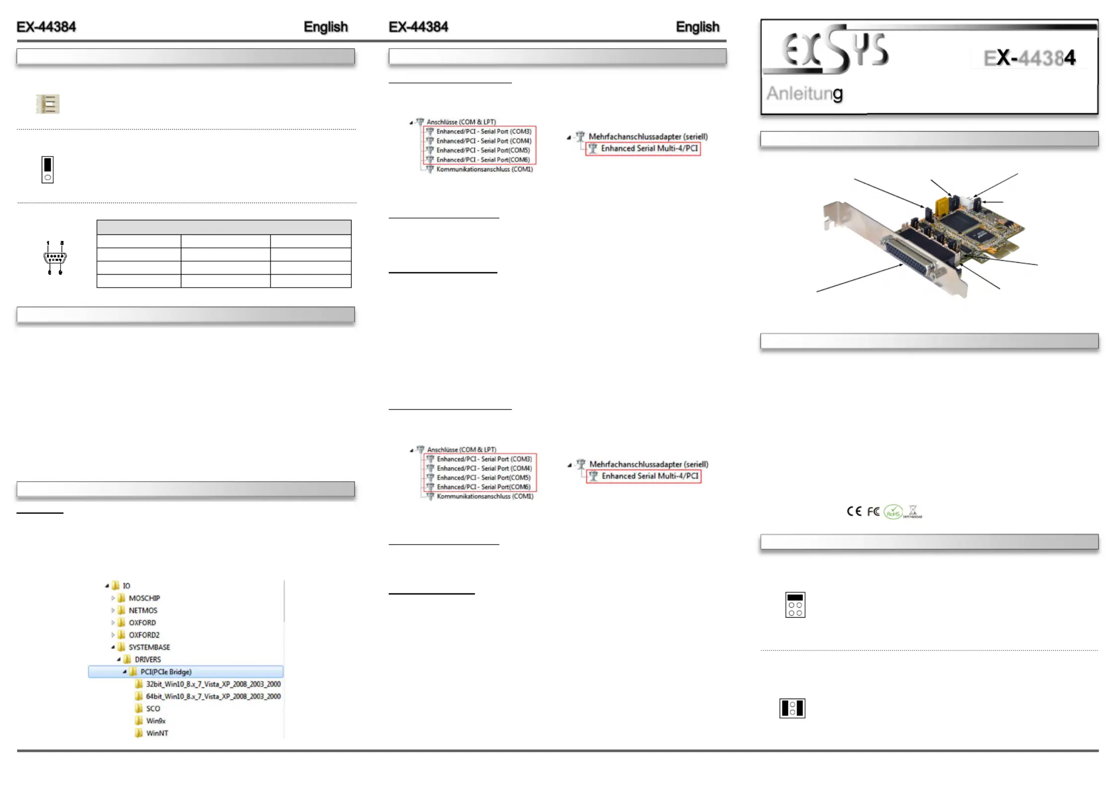
E4438
S1S4:- 44 Pin Stecker zu
4 x 9Pin Serieller
Anschluss
S1~S4PH: -
Interner serieller Anschluss
JP1:Jumper für die Stromquelle
- (Netzteil oder PCIExpress Bus)
J2:Anschluss für Strom
vom PC Netzteil
S1~S4_PWR:
Power auf 9 Pin
Stecker Ein/Aus
JP2: Nur für Testzwecke
(Nicht verändern!)
JP3:PME
Ein / Ausschalten-
JUMPEREINSTELLUNG & ANSCHLÜSSE
RI =Am Pin 9 liegt das Standard Signal RI (Ring Indicator)
(Werkseinstellung)
5 =Am Pin 9 liegt jetzt eine Spannung von DC5V an
12 =Am Pin 9 liegt jetzt eine Spannung von DC12V an
Die Einstellung der Spannung nehmen Sie mit dem JP1 vor. Dies sollte
aber bei Standard Anwendungen nicht verstellt werden.
JP1:
Wenn Sie den Jumper S1~S4_PWR auf 5 oder 12 gesetzt haben,
können Sie mit dem Jumper JP1 den Spannungswert einstellen. Es gibt
3 verschiedene Spannungsquellen.
(Nur in Verbindung mit S1~S4_PWR auf 5 oder 12!!!)
X5(Werkseinstellung) -=5Volt vom PCNetzteil
X12 - =12Volt vom PCNetzteil
I12(Werkseinstellung) =12Volt vom Mainboard
I12 X12 X5
S1~S4_PWR:
RI
5
12
JUMPERSETTING & CONNECTORS
HARDWAREINSTALLATION
If you are ready with the jumper settings, please proceed with the following installation instructions.
Because there are large differences between PC’s, we can give you only a general installation
guide. Please refer to your computer’s reference manual whenever in doubt.
1.Turn off the power to your computer and any other connected peripherals.
2.Remove the mounting screws located at the rear and/ or sides panels of your Computer and
gently slide the cover off.
3.Locate an available expansion slot and remove its covers from the rear panel of your comput-
er. Make sure it is the right expansion slot for the card (see card description)
4.Align the card with the expansion slot, and then gently but firmly, insert the card. Make sure
the card is seated and oriented correctly. Never insert the card by force!
5.Then connect the card with a screw to the rear panel of the computer case.
6.Gently replace your computer’s cover and the mounting screws.
DRIVER INSTALLATION
Windows
After completing the hardware installation, the operating system will automatically the card and
install this! If the driver should not be installed automatically, insert the driver CD into you CD-
ROM drive (eg drive D:) and then open the folder „IO/SYSTEMBASE/DRIVERS/PCI(PCIe
Bridge)“. Please select the folder with your operating system and install the driver (see Picture).
Follow the hardware assistant and finish the installation. Important! Restart your PC in any
case after installing the drivers.
DRIVER INSTALLATION
CHECK INSTALLED DRIVER
Open the >Device manager<. Now you should see at „“ and at Ports (COM & LPT)
„“ the following new entry's:Multifunction Adapter
If you see this or a similar information the device is installed correctly.
CHANGE PORT NUMBER
If you like to change the port number for example COM3 to COM5, open the „Device Manager ”
click at „COM3”,Settings„”and then „Advance”. There you can change between COM3 till
COM256.
Windows Server 20xx
After completing the hardware installation, the operating system will automatically the card and
install this! If the driver should not be installed automatically, insert the driver CD into you CD-
ROM drive (eg drive D:) and then open the folder „IO/SYSTEMBASE/DRIVERS/PCI(PCIe
Bridge)“. Please select the folder with your operating system and install the driver (see Picture).
Follow the hardware assistant and finish the installation. Restart your PC in any Important!
case after installing the drivers.
Use the following driver for the following Windows Server Version.
Windows Server 2003=XP Driver
Windows Server 2008=VISTA Driver
Windows Server 2008R2=Windows 7 Driver
Windows Server 2012=Windows 8.x Driver
Windows Server 2012R2=Windows 10 Driver
CHECK INSTALLED DRIVER
Open the >Device manager<. Now you should see at „“ and at Ports (COM & LPT)
„“ the following new entry's:Multifunction Adapter
If you see this or a similar information the device is installed correctly.
CHANGE PORT NUMBER
If you like to change the port number for example COM3 to COM5, open the „Device Manager ”
click at „COM3”,Settings„”and then „Advance”. There you can change between COM3 till
COM256.
Linux / SCO Unix
The drivers are located in the following folder on our driver CD:
"IO/SYSTEMBASE/DRIVERS/PCI(PCIe Bridge)/SCO"
Because each individual distribution and kernel version of Linux is different, sadly we cant
provide a installation instruction. Please refer to the installation manual for standard IO ports
from your Unix/Linux version! In some newer versions of Linux the card will even be installed
automatically after starting Linux.
J2:
1 +5V
2 GND
3 GND
4 +12V
For aux power (JP1), J2 must be connected to pc power supply! If not
the card won’t work.
DB 9M:
PinSignalPinSignalPinSignal
1CDC4DTR7RTS
2RXD5GROUND8CTS
3TXD6DSR9RI
Serial 9 Pin DSUB Connector-
JP3:
DIS
ENA
DIS = The function PME is disable. (Factory Setting)
ENA= The function PME is enable. Now the card can be activate
the computer through the serial ports.
But this should not be adjusted for standard applications.
Produktspecifikationer
| Varumärke: | EXSYS |
| Kategori: | ej kategoriserat |
| Modell: | EX-44384 |
| Vikt: | 800 g |
| Bredd: | 89 mm |
| Höjd: | 66 mm |
| Värdgränssnitt: | PCIe |
| Serveroperativsystem som stöds: | Windows Server 2012 R2 |
| Monteringsfästen ingår: | Ja |
| Seriellt gränssnitt: | RS-232 |
| Databitar: | 5, 6,7, 8 |
| bruksanvisning: | Ja |
| Temperatur vid drift: | 0 - 55 ° C |
| Temperaturintervall (förvaring): | -40 - 75 ° C |
| Intervall för relativ operativ luftfuktighet: | 5 - 95 % |
| Plug & Play-kompatibel: | Ja |
| Linux operativsystem som stöds: | Ja |
| Intern: | Ja |
| Kretsar: | SB16C1054PCI |
| Flödeskontroll: | Ja |
| Ändamål: | PC |
| Utgränssnittet: | VGA |
| Drivrutiner medföljer: | Ja |
| stoppbitar: | 1, 1.5, 2 |
| Expansionskortets standard: | PCIe 3.0 |
Behöver du hjälp?
Om du behöver hjälp med EXSYS EX-44384 ställ en fråga nedan och andra användare kommer att svara dig
ej kategoriserat EXSYS Manualer

25 September 2025
25 September 2025
30 Juli 2025
29 Juli 2025
29 Juli 2025
29 Juli 2025
29 Juli 2025
29 Juli 2025
29 Juli 2025
29 Juli 2025
ej kategoriserat Manualer
Nyaste ej kategoriserat Manualer
3 April 2026
3 April 2026
3 April 2026
3 April 2026
3 April 2026
3 April 2026
3 April 2026
3 April 2026
3 April 2026