Festo KSK-A-70 Bruksanvisning
Festo ej kategoriserat KSK-A-70
Läs gratis den bruksanvisning för Festo KSK-A-70 (4 sidor) i kategorin ej kategoriserat. Guiden har ansetts hjälpsam av 39 personer och har ett genomsnittsbetyg på 4.4 stjärnor baserat på 5 recensioner. Har du en fråga om Festo KSK-A-70 eller vill du ställa frågor till andra användare av produkten? Ställ en fråga
Sida 1/4
Translation of the original instructions
1Further applicable documents
All available documents for the product èwww.festo.com/pk.
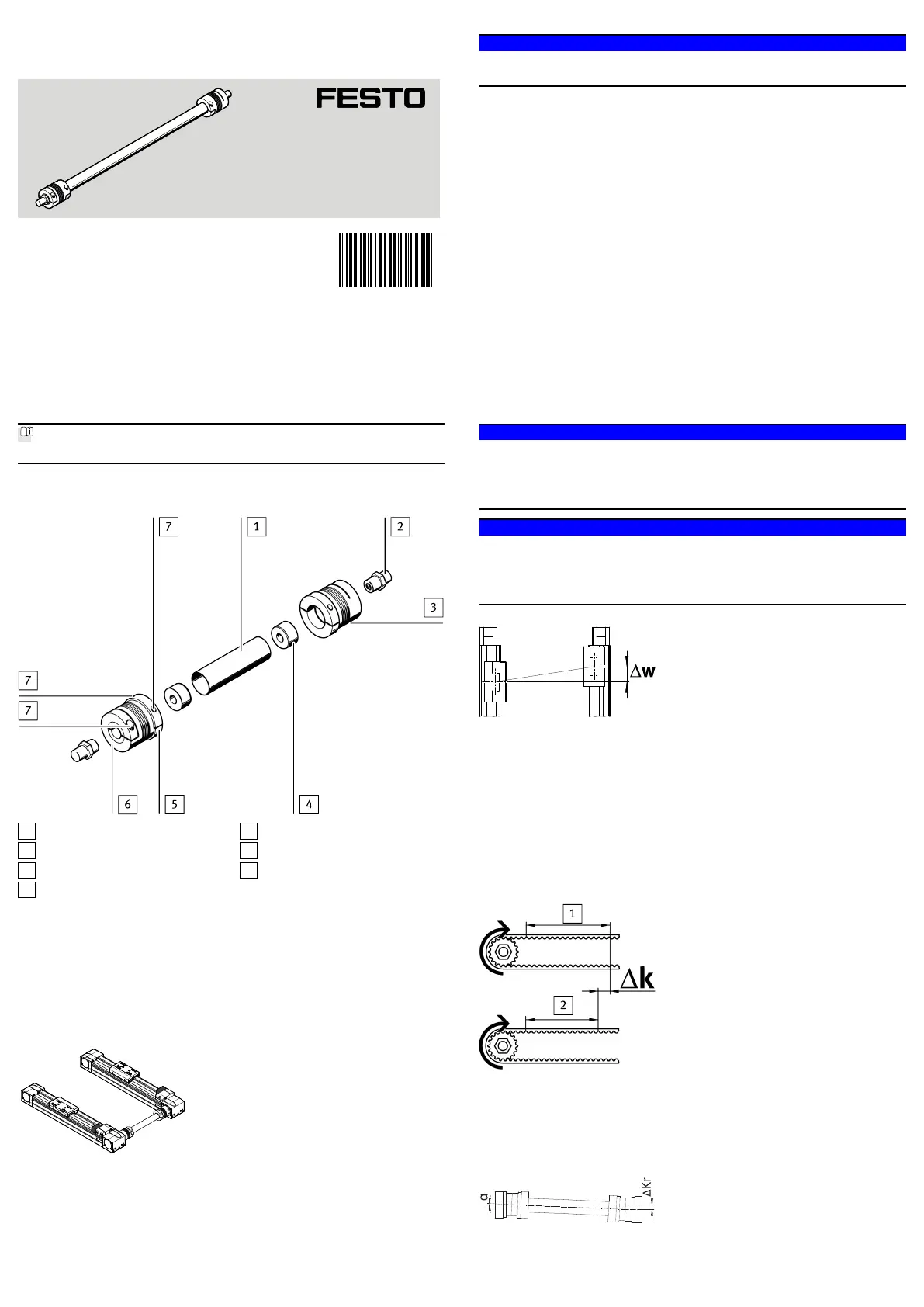
2Operating elements and connections
1
Connecting tube
2
Drive shaft
3
Coupling
4
Plug (only for KSK-185)
5
Half shells (split hub)
6
Unsplit hub
7
Coupling screws
Fig. 1
3Function and application
The KSK connecting shaft synchronises the rotary motion of two parallel electric
toothed belt axes.
It is intended for transmission of rotary motion without additional external loads
in horizontal mounting position of the connecting shaft between axes EGC-...-TB
or ELGA-TB.
Fig. 2 Mounting position (example)
4Transport and storage
Store the connecting shaft preferably at room temperature without external mech-
anical loads. Temperature stresses and extreme climatic conditions will damage
the couplings in particular.
5Requirements for product use
NOTICE!
•Make sure that the items in this chapter are observed at all times.
This ensures that the product operates correctly and safely.
–Take into consideration the legal regulations applicable for the location as
well as:
–Instructions and standards
–Regulations of testing organisations and insurers,
–National specifications.
–Compare the limit values specified in these operating instructions with your
actual application (e.g. installation tolerances, forces, torques, temperatures,
masses, velocities).
Operation of the product in compliance with the relevant safety regulations
depends on adherence to the load limits.
–Remove transport packaging, such as films, caps and cardboard.
The material used in the packaging has been specifically chosen for its recyc-
lability (exception: oiled paper = residual waste).
–Use the product in its original status, without any unauthorised modifica-
tions.
–Take into consideration the ambient conditions at the location of use.
Corrosive environments (e.g. ozone) will reduce the service life of the
product.
–Take the tolerance of the tightening torques into account. Unless otherwise
specified, the tolerance is ±20%.
6Installation
NOTICE!
Damaged shafts may lead to failure of axis synchronisation.
•Check whether the connecting shaft has transport or bearing damage, in par-
ticular kinks, dents or bends. A KSK with such damage is not suitable for fur-
ther use.
NOTICE!
Damaged metal bellows of the couplings may lead to failure of axis synchron
isation.
•Check whether the metal bellows of the coupling show kinks, dents or out-of-
roundness. A coupling with such damage is not suitable for further use.
Fig. 3
•Make sure that the maximum permissible static slide misalignment Δw of the
axes is
è 12.2 Max. permissible static slide misalignment at permissible drive
torquemaintained over the entire travel distance. The diagram is already
reduced by the dynamic component of the misalignment caused by the shaft
torsion.
The slide offset Δw is made up of the offset of:
–different slide feeds Δk
–due to mounting tolerances.
Fig. 4
•To determine the offset Δk, measure the travel distances 1 k1 and 2k2 of
the slides on both axes with the same number of revolutions of the drive
shafts (preferably over the entire stroke range).
The offset Δk results from the distance difference.
Fig. 5
8106170
KSK
Connecting shaft
8106170
2019-07f
[8106172]
Instructions| Operating
Festo SE & Co. KG
Ruiter Straße 82
73734 Esslingen
Germany
+49 711 347-0
www.festo.com
Produktspecifikationer
| Varumärke: | Festo |
| Kategori: | ej kategoriserat |
| Modell: | KSK-A-70 |
Behöver du hjälp?
Om du behöver hjälp med Festo KSK-A-70 ställ en fråga nedan och andra användare kommer att svara dig
ej kategoriserat Festo Manualer

21 Oktober 2025
21 Oktober 2025
21 Oktober 2025
21 Oktober 2025
21 Oktober 2025
21 Oktober 2025
21 Oktober 2025
21 Oktober 2025
21 Oktober 2025
21 Oktober 2025
ej kategoriserat Manualer
Nyaste ej kategoriserat Manualer
3 April 2026
3 April 2026
3 April 2026
3 April 2026
3 April 2026
3 April 2026
3 April 2026
3 April 2026
3 April 2026