Gira 5502910 Bruksanvisning
Gira internt kommunikations system 5502910
Läs gratis den bruksanvisning för Gira 5502910 (3 sidor) i kategorin internt kommunikations system. Guiden har ansetts hjälpsam av 57 personer och har ett genomsnittsbetyg på 4.3 stjärnor baserat på 2 recensioner. Har du en fråga om Gira 5502910 eller vill du ställa frågor till andra användare av produkten? Ställ en fråga
Sida 1/3
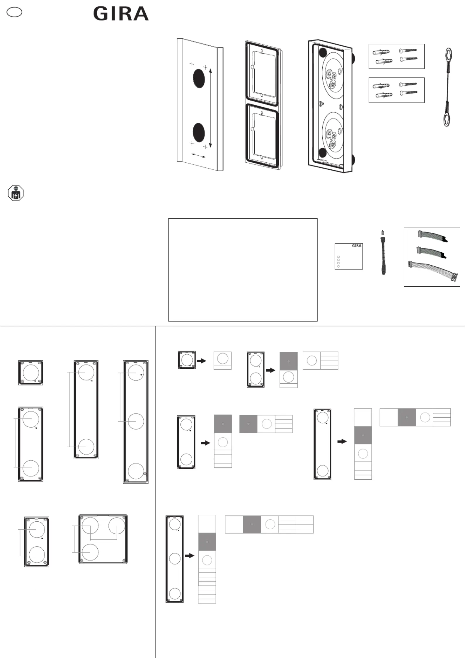
Installation
instructions
1 x 1
Dimensions
1 x 3
1 x 4
1 x 5
220 mm
220 mm
330 mm
a
b
1 x 1 = 106,5 x 106,5 mm
1 x 2 = 106,5 x 213,0 mm
2 x 2 = 213,0 x 213,0 mm
1 x 3 = 106,5 x 319,5 mm
1 x 4 = 106,5 x 426,0 mm
1 x 5 = 106,5 x 532,5 mm
1 x 2
2 x 2
110 mm
110 mm
110 mm
ab
Scope of supply
01
02
03
04
05
06
07
08
1 x
1 x
1 x
2 x
1 x
1 x
1 x
1 x
Drilling template
Function carrier
Housing
Screw and dowel set
(ø 6 mm)
Safety bond
Bit holder and bit
Installation instructions
08
4020
05
06
Gehäuse Aufputz 1 bis 5fach
de
Gehäuse Aufputz 1 bis 5fach
Gehäuse Aufputz 1 bis 5fach
Gehäuse Aufputz 1 bis 5fach
fr
en
nl
03
07
01
Mounting examples
22
22
22
22
10 86 43 62 23/17
System 106
Surface-mounted housing
1-
to 5-gang
5501 9..
5502 9..
5503 9..
5504 9..
5505 9..
5508 9..
For your safety
These instructions are part of the product and
must remain with the end customer.
Read the instructions before use and
observe the information.
Mounting example: surface-mounted housing,
2-gang.
Electrical devices may only be installed and
connected by a qualified electrician.
System cables and
terminating resistors
(from 2-gang housing)
en
Produktspecifikationer
| Varumärke: | Gira |
| Kategori: | internt kommunikations system |
| Modell: | 5502910 |
| Produkttyp: | Ytmonteringsbox |
| Bredd: | 213 mm |
| Djup: | 25.35 mm |
| Höjd: | 106.5 mm |
| Material: | Metall |
| Produktens färg: | Antracit |
| Monteringssätt: | Yta |
| Brand kompatibilitet: | GIRA |
Behöver du hjälp?
Om du behöver hjälp med Gira 5502910 ställ en fråga nedan och andra användare kommer att svara dig
internt kommunikations system Gira Manualer

28 Juli 2025
28 Juli 2025
28 Juli 2025
24 Juli 2025
internt kommunikations system Manualer
Nyaste internt kommunikations system Manualer
22 Mars 2026
13 Mars 2026
10 Mars 2026
9 Mars 2026
9 Mars 2026
8 Mars 2026
8 Mars 2026
6 Mars 2026
16 Februari 2026
10 Februari 2026