Gira 5531920 Bruksanvisning
Gira internt kommunikations system 5531920
Läs gratis den bruksanvisning för Gira 5531920 (2 sidor) i kategorin internt kommunikations system. Guiden har ansetts hjälpsam av 45 personer och har ett genomsnittsbetyg på 4.4 stjärnor baserat på 7 recensioner. Har du en fråga om Gira 5531920 eller vill du ställa frågor till andra användare av produkten? Ställ en fråga
Sida 1/2
General safety instructions
These instructions are part of the product
and must remain with the end customer.
Necessary accessories
•System 106 intercom module (item no.
5555 ..) or door station module (item
no..5565 ..).
•Audio control device (item no. 1287 00).
•Gira home station.
•System 106 surface-mounted housing,
1-gang to 5-gang.
Accessories
•System 106 camera module (item no.
5561 00).
•Video control device (item no. 1288 00) if
using a camera module
•Call-button cover plate for call-button
module (item no. 5541 9xx).
•Start-up key for call-button module (item
no. 5539 00)
Functional description
The call-button module covers the functions
“door call” and “switch” in the Gira door
communication System 106.
Scope of supply
1 x System 106 call-button module
1 x operating instructions
1 x tool for inscription label
Ensure the package contents are complete
and undamaged. When filing complaints,
see "Warranty".
Electrical devices may only be
installed and connected by a
qualified electrician.
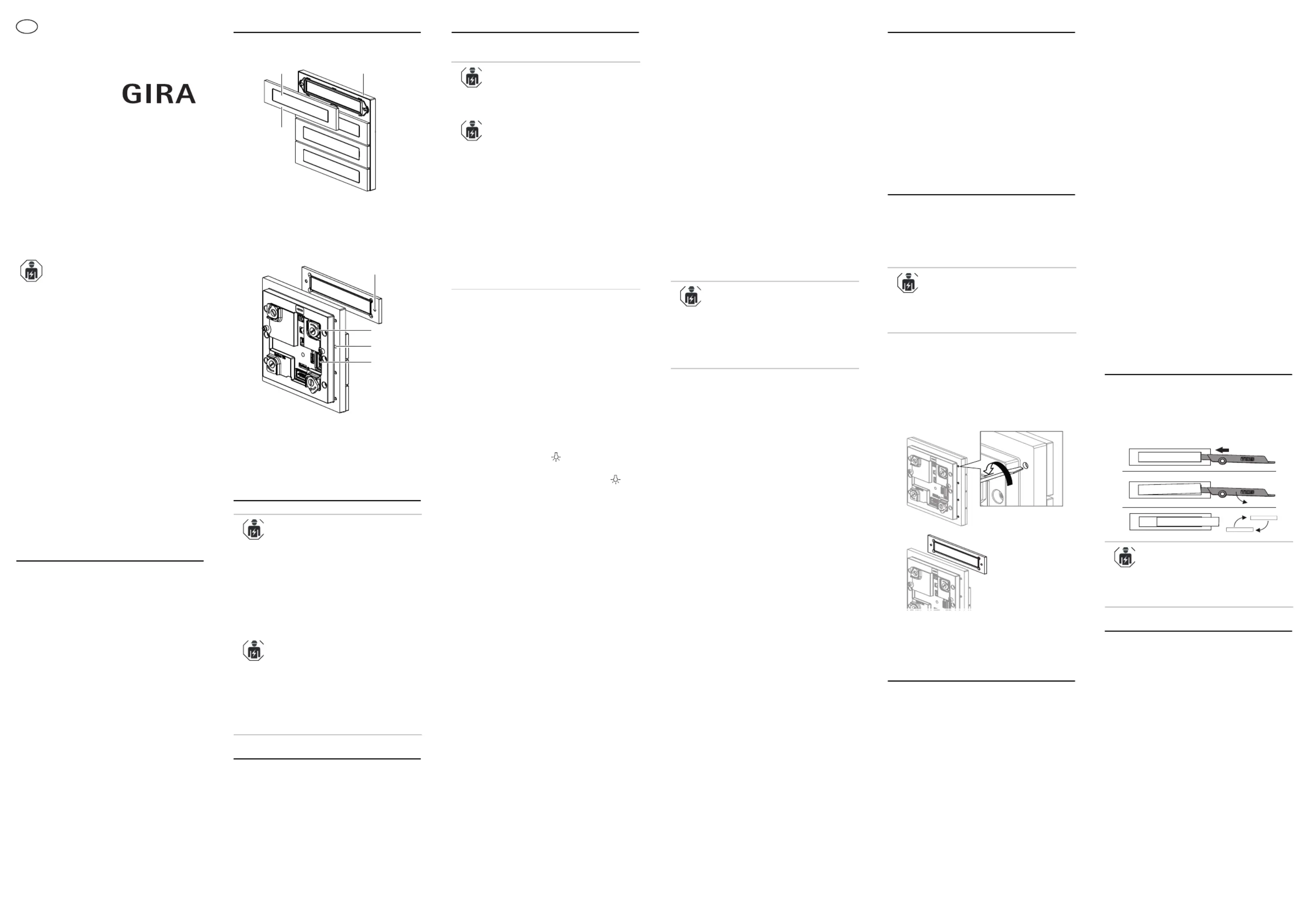
Device description
Front view
Rear view
Installing the module
Starting up the device
The call-button module can only be started
up with an intercom or door station module
with a control device (see “Assigning call
buttons”).
All devices (System 106 module, home
stations, control devices etc.) must be
installed to successful start-up.previous
1Module
2Call button
3Inscription label
1Threaded hole for mounting screw
2Turn-type lock (4 x)
3Fastening screw for call button (non-
removable)
4Slot (2x): System cable
Installing the module
The installation instructions for the
System 106 surface-mounted 1-gang to 5-
gang housing describes the following
working steps:
•Lock the module on the mounting
frame.
•Plug in the connection cable.
•Place terminating resistors.
Terminating resistor
From the 2-gang surface-mounted housing
up, there are always two terminating
resistors included.
The terminating resistors are always
connected to the first and last module on
the system cable.
1
2
3
1
2
3
4
Configuring the module
Assigning call buttons
1.: Start programming Control device
mode; press the “Systemprog.” button
for about 3 s until the LED flashes
(orange).
2.Call-button module: Press the buttons in
the sequence in which the home
stations are to be assigned 3 seconds
each.
3.First call button: A brief
acknowledgement tone can be heard
after 3 s: Release the call button. Then a
long acknowledgement tone sounds.
Repeat step 3 for all other call buttons
than need to be assigned.
4.First home station: Press button for
about 3 s. Release the button after the
first brief acknowledgement tone .
Then a long acknowledgement tone
sounds. The call button has been
assigned to the home station
successfully.
5.Repeat step 4 for all other home
stations.
6.: Exit the programming Control device
mode; press the “Systemprog.” button
briefly until the LED goes out.
Setting the speaker volume
1.: Start programming Control device
mode; press the “Systemprog.” button
for about 3 s until the LED flashes
(orange).
2.: Briefly press the Door station module
already assigned call button.
3.: Accept call and start Home station
voice communication.
4.: Briefly press call Door station module
button again.
Volume control: Press the button during
voice communication to adjust volume
(total of five volume levels;
level 4is preset). Each press of the call
button increases the volume by one
level. (After the highest volume level, the
system cycles to the lowest level.)
5.: End voice Home station
communication. The most recent volume
level is stored in the door station.
6.: Exit the programming Control device
mode; press the “Systemprog.” button
briefly until the LED goes out.
Teaching sequence
Always teach the switching actions first, then
the call buttons.
Optical and acoustic status feedback
via the intercom module
While the programming mode is active, the
intercom module gives the following visual
and acoustic feedback:
•Programming mode started: LED flashes
orange.
•Programming via the call button: Every
3 s, a short acoustic acknowledgement
sounds and the LED flashes green.
•Programming finished: A long acoustic
acknowledgement sound can be heard,
and the LED lights up green.
•Programming mode cancelled: LED goes
out.
Deactivating/activating the acoustic
call button actuation
Acoustic call button actuation is
deactivated by default and is activated
automatically for each assigned call button.
1.: Start programming Control device
mode; press the “Systemprog.” button
for about 3 s until the LED flashes
(orange).
2.: Press and hold any Call-button module
call button for 6 s.
Release the call button after the second
brief acknowledgement tone (= 6 s).
Then a long acknowledgement tone
sounds to indicated that the acoustic
call button actuation is deactivated for
all call buttons.
3.: Exit the programming Control device
mode; press the “Systemprog.” button
briefly until the LED goes out.
Reactivation: Repeat steps 1 to 3.
Backlight
The backlight can be turned on and off for
each call button individually or for all call
buttons collectively.
Switching off the backlight for single
buttons
1.: Start programming Control device
mode; press the “Systemprog.” button
for about 3 s until the LED flashes
(orange).
2.: Press and hold any Call-button module
call button for 9 s. Release the call
button after the third brief
acknowledgement tone (= 9 s). Then a
long acknowledgement tone sounds and
all backlit call buttons are visible. Press
any call button again: The backlight is
switched off for all call buttons of the
module.
3.: Briefly press (no Single call button
acknowledgement tone!) to turn the
backlight back on. Repeat this step for
all call buttons that you would like to be
backlit.
4.: Exit the programming Control device
mode; press the “Systemprog.” button
briefly until the LED goes out.
Switching off the backlight for all buttons
1.: Start programming Control device
mode; press the “Systemprog.” button
for about 3 s until the LED flashes
(orange).
2.: Press and hold a Call-button module
call button for 12 s. Release the call
button after the fourth brief
acknowledgement tone (= 12 s). Then a
long acknowledgement tone sounds.
The backlight is switched off completely.
3.: Exit the programming Control device
mode; press the “Systemprog.” button
briefly until the LED goes out.
Turning the backlight back on: Repeat
steps 1 to 3.
Automatic backlight
When the backlight is active, then the
backlight can be switched on and off
automatically depending on the ambient
light via the voice or door station module.
The backlight is activated by default.
Operating the module
Door call
1.Press the call button to trigger a door
call at the assigned home station. The
button actuation can be confirmed
acoustically (acknowledgement tone) or
visually (backlight).
Light switching (requires switching
actuator)
1.Press call button to turn on the light or
any other consumer connected to the
switching actuator.
Changing the start-up button
Only applies to call button module with
start-up buttons:The start-up buttons must
be swapped for call buttons that can be
labelled individually, or for suitable call
button covers.
1.Open the housing and remove the
mounting frame.
2.Unlock the module and remove it from
the mounting frame.
3.Loosen the screws with a screwdriver
(blade width 2.5 x0.4 mm) and pull off to
the front.
4.Place new call button from the front and
tighten (torque: 0.3 Nm).
5.Re-mount the module in the reverse
order.
Delete functions
Delete acoustic call button actuation
The acoustic call button actuation can be
reset completely for each call-button
module. This makes sense e.g. if a call
button has been incorrectly assigned. The
function of the call buttons is also changed
to switching action.
1.: Start programming Control device
mode; press the “Systemprog.” button
for about 3 s until the LED flashes
(orange).
Call buttons for individual labelling
Call buttons for individual labelling can be
ordered through the Gira labelling service
(www.beschriftung.gira.de).
1.
2.
2.: Press and hold a Call-button module
call button for 15 s. Release the call
button after the fifth brief
acknowledgement tone (= 15 s). Then a
long acknowledgement tone sounds to
indicated that the acoustic call button
actuation is deleted for all call buttons.
3.: Exit the programming Control device
mode; press the “Systemprog.” button
briefly until the LED goes out.
4.Incorrect or no longer needed call button
assignments can be deleted using the
home stations.
To reactivate the acoustic call button
actuation, the call buttons of the module
need to be reassigned.
Deleting all assignments
1.: Start programming Control device
mode; press the “Systemprog.” button
for about 3 s until the LED flashes
(orange).
2.: Press and hold any Call-button module
call button for 18 s. After five short and
one long acknowledgement tone (=
18 s), the assignments of all call buttons
and all call button modules are deleted.
3.: Exit the programming Control device
mode; press the “Systemprog.” button
briefly until the LED goes out.
Replacing the inscription space
Call buttons with inscription space:The
label under the transparent pane can be
exchanged with the included tool without a
need to remove the call button.
Technical data
Labels
Suitably designed labels are available from
the Gira labelling service
(www.beschriftung.gira.de).
Power
supply:Via system (flat
ribbon cable, 10-pin)
Power consumption
Backlight on:
160 mW
Stand-by mode:14 mW
Connections:2x System
Ambient
temperature:-25 °C to +70 °C
ProtectionIP54
Dimensions (W x H):106.5 x 106.5 mm
1.
2.
MAIER
BRAUN
3.
MAIER
BRAUN
MAIER
10864527 40/16
System 106
call-button module
5531 9.. (1-gang)
5532 9.. (2-gang)
5533 9.. (3-gang)
5534 9.. (4-gang)
5539 000 (4-gang with
start-up buttons)
Operating instructions
en
Produktspecifikationer
| Varumärke: | Gira |
| Kategori: | internt kommunikations system |
| Modell: | 5531920 |
| Produkttyp: | Samtalsknapp, modul |
| Bredd: | 106.5 mm |
| Höjd: | 106.5 mm |
| Material: | Rostfritt stål |
| Produktens färg: | Rostfritt stål |
| Temperatur vid drift: | -20 - 70 ° C |
| Monteringssätt: | Yta |
| Brand kompatibilitet: | GIRA |
| Strömförbrukning: | 160 mA |
Behöver du hjälp?
Om du behöver hjälp med Gira 5531920 ställ en fråga nedan och andra användare kommer att svara dig
internt kommunikations system Gira Manualer

28 Juli 2025
28 Juli 2025
28 Juli 2025
24 Juli 2025
internt kommunikations system Manualer
Nyaste internt kommunikations system Manualer
22 Mars 2026
13 Mars 2026
10 Mars 2026
9 Mars 2026
9 Mars 2026
8 Mars 2026
8 Mars 2026
6 Mars 2026
16 Februari 2026
10 Februari 2026