Hager HR520 Bruksanvisning
Hager strömbrytare HR520
Läs gratis den bruksanvisning för Hager HR520 (4 sidor) i kategorin strömbrytare. Guiden har ansetts hjälpsam av 14 personer och har ett genomsnittsbetyg på 4.0 stjärnor baserat på 2 recensioner. Har du en fråga om Hager HR520 eller vill du ställa frågor till andra användare av produkten? Ställ en fråga
Sida 1/4
1
6H 5054.e
HR510
03
1
3
51310
n(A)t(s)
0
0,1
0,3
0,40,513
Reset
Test
5
15
30
45
60
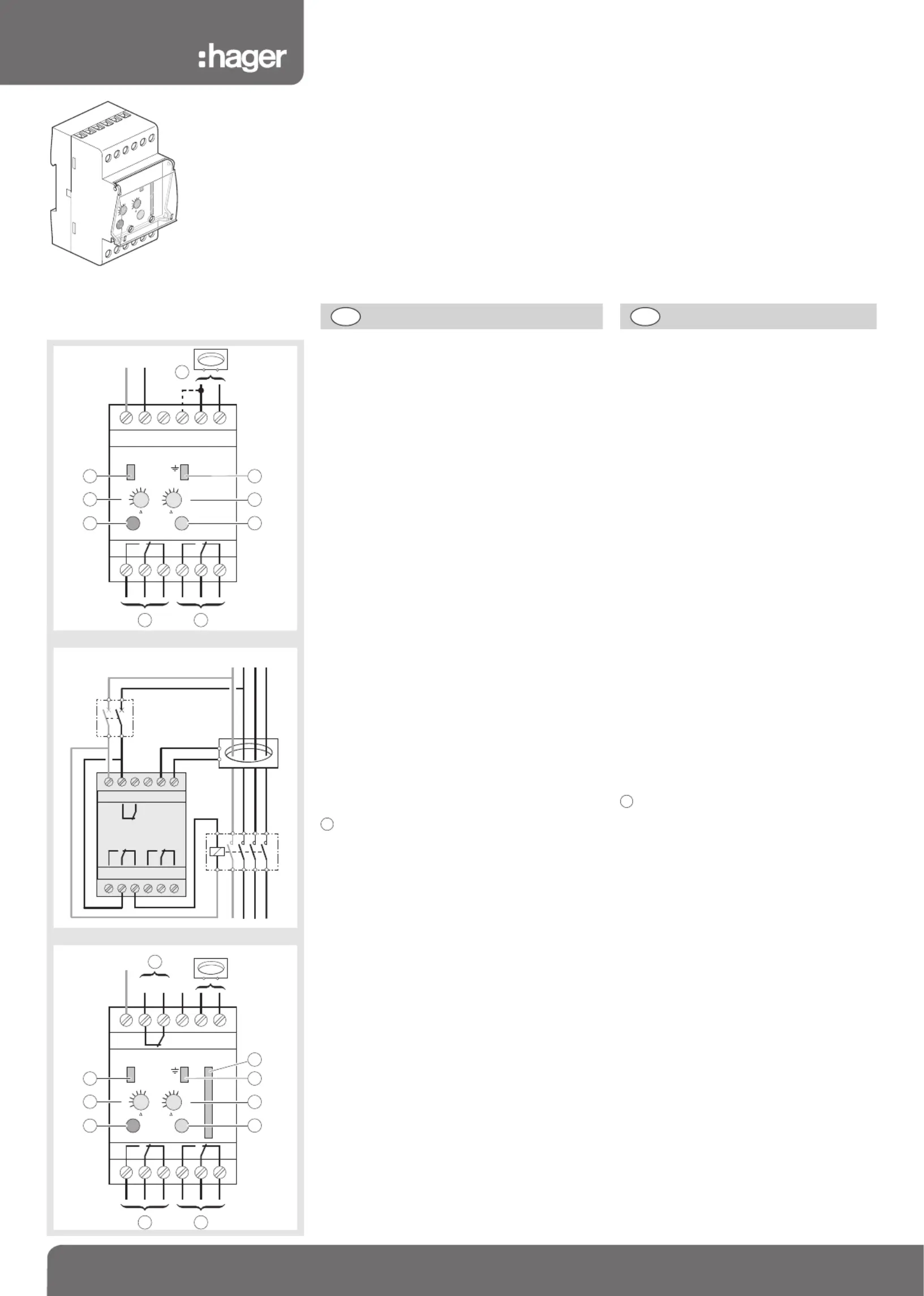
HR510, HR520
Présentation du produit
poussoir “reset” :en cas de déclenchement,
la sortie reste en basculement et le retour à la normale
est obtenu par :
- une impulsion sur le BP d’acquittement “reset”
- une coupure de l’alimentation.
poussoir “test” :l’impulsion sur le BP “test”
permet de vérifier, par une simulation,
le bon fonctionnement du relais en cas de défaut.
voyant de défaut :allumé lors d’un défaut
de l’installation surveillée. Clignotant lors d’une rupture
de la liaison relais/tore.
voyant de présence tension :
bon fonctionnement du produit.
calibres IΔ
Δ
Δ
ΔΔn
temporisation t
Δ
Δ
Δ
ΔΔ
- réglages plombables :toute modification de réglage
peut être proscrite par un capot plombable.
sortie standard (1 OF) :
déclenchement à 85 % de IΔn à ±15 %.
Passe de 0 à 1 lors d’un
- défaut de la liaison tore/relais,
- courant de défaut dans l’installation surveillée.
ou sortie à sécurité positive (1 OF) :
basculement à 1 lors de la mise sous tension,
passe de 1 à 0 lors :
- d’un défaut de liaison tore-relais,
- courant de défaut dans l’installation surveillée,
- défaut d’alimentation ou interne du relais.
sortie à sécurité positive (1 OF) HR520 :
basculement à 1 lors de la mise sous tension,
passe de 1 à 0 lors :
- d’un défaut de liaison tore-relais,
- courant de défaut dans l’installation surveillée
- défaut d’alimentation ou interne du relais.
entrée de sélection du type de sortie :
- pas de connection entres bornes 10 et 11 :
contact
standard.
- connection entre bornes 10 et 11 :
contact
à sécurité positive.
sortie préalarme (1O HR520 ; 1O HR510) :
le contact s’ouvre à 50 % de IΔn (±15 %)
barregraph (HR520) :indique en permanence
la valeur du courant de fuite, 5 à 15 %, 15 à 30 %,
30 à 45 %, 45 à 60 % et 60 à 75 % de IΔn.
Spécifications techniques
Relais :
- Relais : type A ≤ 3 A - type AC > 3 A
- Tension d’alimentation :50/60 Hz 230 V ±20 %
- Tension du réseau contrôlé : 50/60 Hz 50 à 700 V
- Puissance absorbée :5 VA
- Calibres IΔn : 0,03 / 0,1 / 0,3 / 0,5 / 1 / 3 / 10 A
- Temporisation Δt :0 / 0,1 / 0,3 / 0,4 / 0,5 / 1 / 3 s (±20 %)
- Temps de déclenchement :In = 50 msΔ
1,5 à 2,5 In = 40 ms ;Δ
> 2,5 In = 20 msΔ
- Sortie standard (1 OF) :6 A / 250 V AC1
- Sortie sécurité positive (1 OF) : 6 A / 250 V AC1
- Sortie préalarme (1 F) :6 A / 250 V AC1
- Raccordt. des câbles :rigide 1,5
à 10
souple 1
à 6
- Couple de serrage :1,7 Nm
- Longueur maxi liaison test, reset : 20 m (1,5
)
- Longueur maxi liaison tore/relais : 20 m (1,5
)
- T° de stockage :-25 à +70 °C
-T° de fonctionnement :-10 à +55 °C
Tores :
- Surcharge admissible :
5 kA / 1,5 s - 14 kA / 1 s - 100 kA / 0,05 s
- T° de stockage : -25 à +70 °C
-T° de fonctionnement :-10 à +55 °C
11
Normes:
IEC 60 755:2008, IEC 60947-2:2006 annexe M,
IEC 61 543, IEC 61008-1:2010,
IEC 61000-6-1:2005 & IEC 61000-6-3:2006
Standards:
IEC 60 755:2008, IEC 60947-2:2006 annex M,
IEC 61 543, IEC 61008-1:2010,
IEC 61000-6-1:2005 & IEC 61000-6-3:2006
Product presentation
“reset” push button:in case of tripping,
the output remains commutated and the return
to “normal” position is made by:
- pushing the “reset” push button
- a power cut.
“rest” push button:it allows to verify,
by a simulation, the good functioning of the relay
in case of fault.
Fault indicator:it is switched on when fault
of the supervised installation.
Intermittent when there is a breaking of the
relay/torroïd connection.
Supply indicator:good functioning of the product.
Inratings
Δ
Δ
Δ
ΔΔ
Temporization
Δ
Δ
Δ
ΔΔ
t
- sealing adjustments:all modifications of
adjustment can be done by a sealing cover.
Standard output (1 OF) :tripping at 85%
of IΔn ±15 %.
Goes from 0 to 1 when:
- fault when torroïd/relay connection
- fault current when supervised installation.
or positive safety output:
Goes to 1 when supply, goes from 1 to 0 when :
- fault of torroïd/relay connection,
- fault current when supervised installation,
- supply fault or internal relay fault.
Positive safety output (1 OF) HR520 :
Goes to 1 when supply, goes from 1 to 0 when :
- fault of torroïd/relay connection,
- fault current when supervised installation,
- supply fault or internal relay fault.
entrée
Input for changing the output contact :
- no connexion between terminals 10 and 11 :
contact
standard output.
- connexion between terminals 10 and 11 :
contact
positive safety output.
Pre-alarm output (1O HR520 ; 1O HR510) :
the contact opens itself at 50% of In (±15%)Δ
Barregraph (HR520 :indicates continuously
the value of the leakage current,
5 to 15 %, 15 to 30 %, 30 to 45 %, 45 to 60 %
and 60 to 75 % of IΔn.
Technical specifications
Relais :
- Relay : type A ≤ 3 A - type AC > 3 A
- Supply voltage:50/60 Hz 230 V ±20 %
- Supervised power voltage: 50/60 Hz 50 to 700 V
- Consommation: 5 VA
- Ratings IΔn:0,03 / 0,1 / 0,3 / 0,5 / 1 / 3 / 10 A
- Temporization Δt: 0 / 0,1 / 0,3 / 0,4 / 0,5 / 1 / 3 s (±20 %)
- Tripping time:In = 50 msΔ
1,5 to 2,5 In = 40 ms;> 2,5 In = 20 msΔΔ
- Standard output (1OF): 6 A / 250 V AC1
- Positive safety output:(1 OF) : 6 A / 250 V AC1
- Pre-alarm output (1 F): 6 A / 250 V AC1
- Cables connectio : rigid 1,5
to 10
flexible 1
to 6
- Torque setting: 1,7 Nm
- Maxi length of test/reset connection: 20 m (1,5
)
- Maxi length of torroïd/relay connection: 20 m (1,5
)
- Storage temperature:-25 to +70 °C
-Functioning temperature: -10 to +55 °C
Torroïds :
- Allowed overload:
5 kA / 1,5 s - 14 kA / 1 s - 100 kA / 0,05 s
- Storage temperature:-25 to +70 °C
-Functioning temperature: -10 to +55 °C
11
789
10
1234
NPh
1112
56
ON
TestReset
In(A)
t(s)
0
0,1
0,3
0,4
0,5
1
3
0,03
0,1
0,3
0,5
1
3
10
1
4
2
7
5
3
6
10
HR510
9
FRGB
789
10
1234
1112
56
N
L1L2L3
6 A6 A
789
10
1234
N
Ph
1112
56
5
15
30
45
60
75
ON
TestReset
In(A)
t(s)
0
0,1
0,3
0,4
0,5
1
3
0,03
0,1
0,3
0,5
1
3
10
1
4
2
7
5
3
6
11
8
10
HR520
HR510
HR520
¢
§
£
ß
®
Relais différentielsNotice d’instructions
Earth leakage relayUser instructions
FI-RelaisBedienungsanleitung
Relés diferencialesManual de instrucciones
Relés diferenciaisInstruções de instalação
Produktspecifikationer
| Varumärke: | Hager |
| Kategori: | strömbrytare |
| Modell: | HR520 |
Behöver du hjälp?
Om du behöver hjälp med Hager HR520 ställ en fråga nedan och andra användare kommer att svara dig
strömbrytare Hager Manualer

10 September 2025
10 September 2025
10 September 2025
10 September 2025
10 September 2025
10 September 2025
10 September 2025
10 September 2025
19 Juni 2025
19 Juni 2025
strömbrytare Manualer
Nyaste strömbrytare Manualer
12 September 2025
31 Augusti 2025
31 Augusti 2025
20 Augusti 2025
14 Augusti 2025
13 Augusti 2025
4 Augusti 2025
4 Augusti 2025
4 Augusti 2025
4 Augusti 2025