LawnMaster NPTGCP2517B Bruksanvisning

LawnMaster Grastrimmer NPTGCP2517B

Läs nedan 📖 manual på svenska för LawnMaster NPTGCP2517B (85 sidor) i kategorin Grastrimmer. Denna guide var användbar för 12 personer och betygsatt med 4.5 stjärnor i genomsnitt av 2 användare

Sida 1/85
Operator's Manual / Manual del usuario
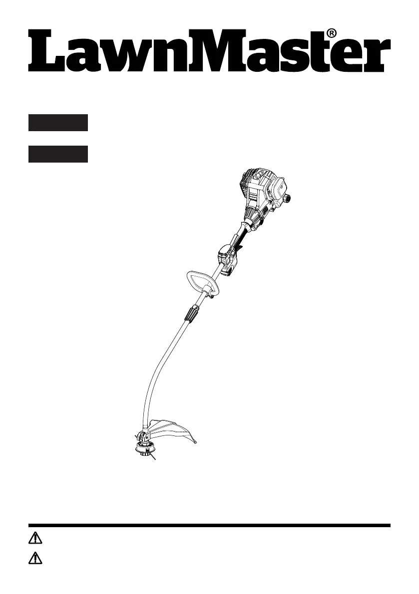
25cc 2-Cycle Grass Trimmer NPTGCP2517B
Bordeadora con Motor de 2 Tiempos de 25 cc NPTGCP2517B
EN p. 2
Read all safety rules and instructions carefully before operating this tool.
601 Regent Park Court Greenville, SC 29607, SC 29650 1-866-384-8432
Lea con cuidado todas las reglas e instrucciones de seguridad antes de utilizar esta herramienta.
601 Regent Park Court Greenville, SC 29607, SC 29650 1-866-384-8432
NOTICE:
Only use unleaded gasoline containing up to 10% ethanol. Do not use E15 or E85 fuel in this trimmer.
It will violate the federal law, damage the trimmer and void your warranty.
AVISO:
Utilice solo gasolina sin plomo que contenga un máximo de 10 % de etanol. No utilice combustible
E15 o E85 con esta bordeadora. Esto violará la ley federal, dañará la bordeadora y anulará su
garantía.
ES p. 44
2
Section Page
25cc-2 CYCLE GRASS TRIMMER
CONTENTS
PRODUCT SPECIFICATIONS
CONTENTS
PRODUCT SPECIFICATIONS
GENERAL SAFETY RULES
SYMBOLS
KNOW YOUR GRASS TRIMMER
ASSEMBLY
BATTERY PACK AND CHARGER
OPERATION
MAINTENANCE
ENVIRONMENTALLY SAFE BATTERY DISPOSAL
TROUBLESHOOTING
WARRANTY
EXPLODED VIEW
PARTS LIST
EXPLODED VIEW 25CC 2-CYCLE ENGINE
PARTS LIST 25CC 2-CYCLE ENGINE
NOTES
2
3-6
7-8
9-10
11-15
16-17
18-25
26-33
34
35-36
37
38
39
40
41
42-43
Engine Type
Engine Displacement Claimed / Rated
Power / Speed
Idle Speed
Max Torque / Speed
Fuel Tank Capacity
Fuel / Oil Ratio
Line Diameter
Cutting Width
Dry Weight
Battery Model No.
Battery Type
Charger Model No.
Charger Input
Charger Output
Charging Period (Battery Fully Discharged)
2-Stroke / Half Crank
25cc / 25 cm3
0.8 kW / 7500 RPM
3000 ± 300 RPM
1.08 N.m / 6500 RPM
420 ml
40 : 1
0.080" (2.0 mm)
17" (430 mm)
11.68 lbs (5.3 kg)
7LB1331-C
7.2V Lithium-Ion, 1.3 Ah
YLS0042-T084045
100-240V ~ 50/60Hz 0.3A Max
8.4V 450 mA
4-6 Hours
3
READ ALL INSTRUCTIONS AND SAVE THESE INSTRUCTIONS.
Read the Operator’s Manual and follow all warnings and safety instructions. Failure to do so can result
in serious injury to the operator and/or bystanders.
GENERAL SAFETY RULES
WARNING
■ This grass trimmer is designed for cutting grass, soft vegetation.
■ The grass trimmer is intended for residential, or similar landscape use and is not recommended for
use in agricultural or forest environments.
■ This grass trimmer is not suitable for cutting or chopping, otherwise, there is a risk of injury. For
example:
- Hedges, shrubs and bushes,
- Flowers,
- In terms of composting.
■ Never allow children or persons unfamiliar with these instructions to use the trimmer.
■ Do not operate the trimmer inside a closed environment, such as a room or building; breathing
carbon monoxide from exhaust fumes can kill.
■ Clear the work area before each use. Remove all objects such as rocks, broken glass, nails, wire, or
string, which can be thrown or become entangled in the cutting attachment.
■ Clear the area of children, bystanders and pets. At a minimum, keep all children, bystanders and
pets outside a 50 ft (15 m) radius; outside the 50 ft (15 m) zone, there is still a risk of injury from
thrown objects.
■ Bystanders should be encouraged to wear eye protection. If you are approached, stop the engine
and cutting attachment.
Always wear eye protection with side shields marked to comply with ANSI Z87.1 along with hearing
protection when operating this trimmer. Failure to do so could result in objects being thrown into
your eyes and other possible serious injuries.
Always wear heavy, long pants, boots, gloves, and a long-sleeve shirt. Do not wear loose clothing,
jewelry, short pants, sandals, or go barefoot. Secure hair so it is above shoulder level.
■ Do not operate this trimmer when you are tired, ill, upset, or under the inuence of alcohol, drugs, or
medication.
■ Inspect the trimmer before each use. Replace damaged parts. Check for fuel leaks. Make sure all
fasteners are in place and secure.
■ Replace cutting attachment parts that are cracked, chipped, or damaged in any way. Make sure the
cutting attachment is properly installed and securely fastened. Be sure the cutting attachment shield
is properly attached, securely fastened and in the position recommended by the manufacturer.
■ Use only a exible, nonmetallic line recommended by the manufacturer. Never use, for example,
wire or wire-rope, which can break off and become a dangerous projectile.
■ Only use the grass trimmer in daylight or good articial light.
4
GENERAL SAFETY RULES
■ Never operate the grass trimmer with damaged guards or without the guards in place.
■ Maintain a rm grip on both handles while using this tool.
■ Keep rm footing and balance. Do not overreach. Overreaching can result in loss of balance or
exposure to hot surfaces.
■ Maintain stable footing on a solid surface at all times when using the trimmer in order to have better
control of the tool. Do not use the trimmer whilst on a ladder or other unstable support.
■ Keep cutting attachment below waist level. Keep all parts of your body away from the rotating
cutting attachment and hot surfaces.
■ Do not touch mufer, rear cover housing or casing around the engine; these parts get hot whilst and
after the trimmer has been used. Contact with hot surfaces could result in serious burns.
■ The cutting attachment should never rotate at idle during normal use.
■ The cutting attachment may be spinning during carburetor adjustments. Wear your protective
equipment and observe all safety instructions. For units equipped with a clutch, be sure the cutting
attachment stops turning when the engine idles. When the unit is turned off, make sure the cutting
attachment has stopped before the unit is set down.
■ Mix and store fuel in a container approved for storing gasoline.
■ Mix and pour fuel outdoors where there are no sparks and ames. Slowly remove the fuel cap only
after stopping the engine and letting it cool completely. Do not smoke while fueling or mixing fuel.
Wipe spilled fuel from the trimmer. Move at least 10 ft (3 m) away from the fueling source and the
site before starting engine.
Before fueling or storing the tool, stop the engine and allow it to cool completely.
■ Before transporting the tool in a vehicle, allow the engine to cool completely and empty the fuel
tank. Always secure the tool to avoid movement during transportation.
■ Only use replacement parts or accessories provided or listed in this Operator’s Manual.
■ This trimmer is not intended for extended use. Extended periods of operation can cause circulatory
problems in the user’s hands due to the vibration caused by the tool. Take regular breaks from
operating the tool.
Always take your tool to an authorized service center for repair. Service performed by inexperienced
or unqualied persons may damage the tool, create unsafe conditions, increase the risk of personal
injury, and/or void your warranty.
BATTERY PACK
■ The battery pack is compatible with the YLS0042-T084045 charger.
■ Charge the battery only with the charger specied by the manufacturer and listed in this manual. A
charger that is suitable for one type of battery pack may create a risk of re when used with another
battery pack.
■ Do not place battery powered tools or their batteries near re or heat. This will reduce the risk of
explosion and possibly injury.
■ Do not open or mutilate the battery pack. Released electrolyte is corrosive and may cause damage
to the eyes or skin. It may be toxic if swallowed.
5
GENERAL SAFETY RULES
■ Do not dispose of battery packs in re. They will explode or leak and cause injury. Liquid ejected
from the battery may cause irritation or burns.
■ Do not crush, drop or damage the battery pack. Do not use a battery pack or charger that has been
dropped or received a sharp blow. A damaged battery is subject to explosion. Properly dispose of a
dropped or damaged battery immediately.
■ Batteries can explode in the presence of a source of ignition, such as a pilot light. To reduce the
risk of serious personal injury, never use any cordless product in the presence of open ame. An
exploded battery pack can propel debris and chemicals. If exposed, ush with water immediately.
■ Under extreme usage or temperature conditions, battery pack leakage may occur. If liquid comes in
contact with your skin, wash immediately with soap and water, then neutralize with lemon juice or
vinegar. If liquid gets into your eyes, ush them with clean water for at least 10 minutes, then seek
immediate medical attention.
■ When the battery pack is not in use, keep it away from other metal objects like: paper clips, keys,
nails, screws, or other small metal objects that can make a connection from one terminal to another.
Shorting the battery pack terminals together may cause sparks, burns, or a re.
■ Do not expose a battery pack to re or excessive temperature. Exposure to re or temperature
above 265°F (130°C) may cause an explosion.
■ Do not modify or attempt to repair the battery pack (as applicable) except as indicated in the
instructions for use and care.
■ Follow all charging instructions and do not charge the battery pack outside the temperature range
specied in the instructions. Charging improperly or at temperatures outside of the specied range
may damage the battery and increase the risk of re.
BATTERY CHARGER
■ This charger is compatible with a 7LB1331-C or 07LB2001-S lithium-ion battery.
■ To reduce the risk of injury, charge only the specied lithium-ion rechargeable batteries. Other types
of batteries may burst, causing personal injury or damage.
■ Do not charge the battery in a damp or wet location. Following this rule will reduce the risk of electric
shock.
■ Keep the cord and charger away from heat to prevent damage to housing or internal parts.
■ Do not operate charger with a damaged cord or plug, which could cause shorting and electric shock.
If damaged, immediately discontinue use. Replace the charger with an identical model as listed in
this manual.
■ Do not use a charger that has been dropped or received a sharp blow.
■ Do not disassemble charger. Take it to a qualied service center to be checked or replaced.
Incorrect reassembly may result in a risk of electric shock or re.
■ Do not abuse the charger cord. Never use the cord for carrying, pulling or unplugging.
■ Keep the cord away from heat, oil, sharp edges or moving parts. Damaged or entangled cords
increase the risk of electric shock. If the charger cord is damaged, replace the charger with an
6
GENERAL SAFETY RULES
identical model as listed in this manual.
A charger that is suitable for one type of battery pack may create a risk of re when used with
another battery pack.
■ Charge the battery at the normal charging temperature between 40°F (4°C) and 100°F (38°C).
FCC COMPLIANCE
■ This device complies with Part 15 of the FCC Rules. Operation is subject to the following two
conditions:
- This device may not cause harmful interference, and
- This device must accept any interference received, including interference that may cause
undesired operation.
NOTE: This equipment has been tested and found to comply with the limits for a Class B digital device,
pursuant to Part 15 of the FCC Rules. These limits are designed to provide reasonable protection
against harmful interference in a residential installation.
■ This equipment generates, uses and can radiate radio frequency energy and, if not installed and
used in accordance with the instructions, may cause harmful interference to radio communications.
However, there is no guarantee that interference will not occur in a particular installation. If
this equipment does cause harmful interference to radio or television reception, which can be
determined by turning the equipment off and on, the user is encouraged to try to correct the
interference by one or more of the following measures:
- Reorient or relocate the receiving antenna.
- Increase the separation between the equipment and receiver.
- Connect the equipment into an outlet on a circuit different from that of the receiver.
- Consult the dealer or an experienced radio/ TV technician for help.
SAVE THESE INSTRUCTIONS
Refer to them frequently and use them to instruct others who may use this product. If you loan someone
this product, loan them these instructions also.
The engine exhaust from this product can expose you to chemicals including carbon monoxide, which
is known to the State of California to cause cancer, birth defects, or other reproductive harm. To reduce
the risk of serious or fatal injury/illness, never run the machine indoors or in poorly ventilated locations.
For more information go to www.P65Warnings.ca.gov.
WARNING
8
SYMBOLS
Keep Away From Water Do not dispose of battery packs in rivers or immerse in
water.
Keep Away From Fire Do not dispose of battery packs in fire. They will
explode or leak and cause injury.
Heat Alert Do not expose battery packs to heat in excess of
140°F (60°C).
Recycle Symbol
This product uses lithium-ion batteries. Local, state,
or federal laws may prohibit disposal of batteries in
ordinary trash. Consult your local waste authority for
information regarding available recycling and/or
disposal options.
SYMBOL SIGNAL MEANING
DANGER Indicates an imminently hazardous situation, which, if not
avoided, will result in death or serious injury.
WARNING Indicates a potentially hazardous situation, which, if not
avoided, could result in death or serious injury.
CAUTION Indicates a potentially hazardous situation, which, if not
avoided, may result in minor or moderate injury.
NOTICE (Without Safety Alert Symbol) Indicates a situation that may
result in property damage.
The following signal words and meanings are intended to explain the levels of risk
associated with this product.
Close
Open
Close the choke.
Open the choke.
10
KNOW YOUR GRASS TRIMMER
Components
1. Choke Lever
2. Primer Bulb
3. Air Filter Cover
4. Fuel Tank Cap
5. Fuel Tank
6. Main Handle
7. Stop Switch
8. Battery Slot
9. Battery Release Button
10. Locking Collar
11. Shaft
12. Debris Guard
13. Trimmer Line
14. Trimmer Head With Line Spool
15. Assist Handle
16. Start Button
17. Battery Indicator
18. Throttle Safety
19. Engine Housing
20. Spark Pulg Cap
21. Start Button Cover
22. Trimmer Line Cutting Blade
23. Shaft Connection Sleeve
24. Throttle Lever
25. Mufer
26. Charging Port
27. Battery Pack
28. Charger
29. Charging Connector
The safe use of this product requires an understanding of the information on the product and in this
Operator’s Manual as well as knowledge of the project you are attempting. Before use of this product,
familiarize yourself with all operating features and safety rules.
26
27
28
29
12
ASSEMBLY
FITTING THE DEBRIS GUARD (See Figs. 1-3)
Loosen and remove the screw from the debris guard using the screwdriver provided.
Starting from the top of the split shaft, slide the debris guard all the way down to the correct mounting
position as shown (Fig. 1).
Align the screw hole on the debris guard with the screw hole on the bracket. Insert the screw through the
debris guard and the bracket on the shaft (Fig. 2).
Secure the screw tight using the screwdrive (Fig. 3).
INSTALLING AND REMOVING THE SHAFT (See Figs. 4-6)
To install the shaft:
Turn the locking collar counter-clockwise to remove it from the shaft connection sleeve. Slide the locking
collar onto the shaft.
Check to ensure the axles in the shafts are aligned as shown (Fig. 4). If not aligned, slightly rotate the
trimmer head to adjust the axle until it aligns.
WARNING
The trimming line cutting blade on the debris guard is sharp and is tted with a blade protection lm
which will need to be removed prior to using the trimmer. When tting the guard avoid contact with
the blade. Failure to avoid contact can result in serious personal injury.
WARNING
Never install, remove, or adjust any attachment while the engine is running. Failure to stop the engine
can cause serious personal injury.
Fig. 1 Fig. 2 Fig. 3
Hole on the
debris guard
Hole on the
bracket
13
To remove the shaft:
Stop the engine and remove the battery pack.
Loosen the locking collar by turning counter-clockwise, and pull away from the connection sleeve.
Pull out the shaft to remove.
WARNING
Never adjust the assist handle while the trimmer head is running. Failure to stop the engine may cause
serious personal injury.
Slide the shaft into the shaft connection sleeve, then slide the locking collar onto the connection sleeve to
lock into place (Fig. 5).
Secure the shaft by turning the locking collar clockwise (Fig. 6).
ASSEMBLY
WARNING
Ensure that the locking collar is fully tightened before operating the tool; check it periodically for
tightness during use to avoid serious personal injury.
INSTALLING AND ADJUSTING THE ASSIST HANDLE (See Figs. 7-10)
Loosen and remove the screw bolt and wing nut.
Fix the assist handle onto the shaft as shown by rmly pushing the handle onto the shaft. Make sure that
the groove side faces the engine (Fig. 7).
Adjust the assist handle to your desired position. The assist handle can only be moved in the direction
between the arrow marked "Handle Position" and shaft connection sleeve (Fig. 8).
Fig. 4
Fig. 5 Fig. 6
15
INSTALLING AND REMOVING THE BATTERY PACK (See Figs. 11-12)
To install the battery pack:
Align the battery pack with the battery slot.
Insert the battery pack into the battery slot until the battery pack secures into place. Make sure the battery
is inserted in the correct direction (Fig. 11).
Do not use force when inserting the battery pack. It should slide into position and "click".
To remove the battery pack:
Press and hold the battery release button (Fig. 12).
Slide the battery pack from the battery slot.
WRONG
ASSEMBLY
Fig. 11 Fig. 12
16
BATTERY PACK AND CHARGER
BATTERY CHARGING
■ Use with 8.4V LawnMaster® YLS0042-T084045 battery charger. The battery charger supplied is
specically designed for the lithium-ion battery used in this tool.
■ Check the power voltage! Battery chargers operate on 100-240V AC.
■ Charge the battery between 40°F (4°C) and 100°F (38°C) to ensure an optimum battery service life.
■ Protect the battery from heat, from continuous exposure to sun, and keep away from radiation or
other heat sources. Do not leave the battery in the tool in direct sunlight over long periods.
■ The battery is supplied uncharged. Fully charge the battery before using the tool for the rst time.
The lithium-ion battery can be charged at any time without reducing its service life. Interrupting the
charging procedure does not affect the battery.
CHARGER LEDS
■ If the battery is not connected to the charger, a continuous green LED light indicates that the plug is
plugged into an outlet socket and the battery charger is ready for operation.
■ Charging: a continuous red LED on the charger indicates that the battery is charging normally.
■ Charged: a continuous green LED on the charger indicates that the battery is ready for use.
After continuous or repeated charging cycles without interruption, the charger may warm up. This is
normal and does not indicate a technical defect of the battery charger.
CHARGING THE BATTERY PACK (See Figs. 13-14)
INDICATOR LIGHTS STATUS
Green, continuous Fully charged / Connected to
power supply (Standby)
Red, continuous Charging
WARNING
If any part of the charger is missing or damaged, do not operate it! Replace the charger with a new
one. Failure to heed this warning could result in possible serious injury.
Check the voltage! The voltage must comply with the information on the rating label.
17
BATTERY PACK AND CHARGER
Insert the charging connector into the charging port on the battery (Fig. 13).
Connect the charger to the power supply.
Allow sufcient charging time (see Product Specications), and then disconnect the charger from the power
supply.
Remove the charging connector from the charging port (Fig. 14).
NOTE: It is normal for the battery pack and the charger to become warm (but not hot) during the charging
process. If the battery does not charge properly, check to make sure the electrical outlet is operational. Always
charge the battery before storage!
Fig. 13 Fig. 14
18
OPERATION
WARNING
DANGER
WARNING
WARNING
Do not allow familiarity with products to make you careless. Remember that a careless fraction of a
second is sufcient to inict serious injury.
The fuel is VERY ammable. Use extreme care when mixing, storing or handling, or serious
personal injury may result.
Always wear eye protection with side shields marked to comply with ANSI Z87.1, along with head
protection. Failure to do so could result in objects being thrown into your eyes and other possible
serious injuries.
Do not use any attachments or accessories not recommended by the manufacturer or retailer of this
product. The use of attachments or accessories not recommended can result in serious personal
injury. Before each use, inspect the entire product for damaged, missing, or loose parts such as
screws, nuts, bolts, caps, etc. Tighten securely all fasteners and caps and do not operate this product
until all missing or damaged parts are replaced.
HANDLING THE FUEL
Mix and store in a container approved for storing fuel.
■ DO NOT smoke when handling or close to fuel.
■ DO NOT allow ames or sparks near the fuel.
■ Maintain the pressure in the fuel tank; always loosen the fuel tank cap slowly allowing the
pressure to equalize. NEVER refuel a trimmer when the engine is HOT or RUNNING!
■ DO NOT ll fuel tanks indoors. ALWAYS ll fuel tanks outdoors over bare ground.
■ DO NOT overll the fuel tank and clean up spills immediately.
■ Securely tighten the fuel tank cap and close the fuel container after refueling.
■ Check for fuel leakages. If a fuel leakage is present, remove the battery and do not use the
19
OPERATION
trimmer until the leakage is repaired.
■ Move at least 10 ft (3 m) from refueling location before starting the engine.
FUEL MIXTURE (See Fig. 15)
This trimmer is powered by a 2-cycle engine; the operator is required to use premixed gasoline and
2-cycle lubricant. Prepare a mixture of unleaded gasoline and 2-cycle engine lubricant in a clean
container approved for storing gasoline. Only prepare quantities that can be used up within a few days.
DO NOT prepare quantities that will need to be stored for more than 30 days.
Recommended Fuel
This engine is certied to operate on unleaded gasoline intended for automotive use.
U.S. EPA regulations make it illegal to use gasoline containing higher than 10% ethanol content
in outdoor power equipment like your LawnMaster
® power equipment and doing so can void your
LawnMaster® Limited Warranty.
If the proper precautions are taken, however, gasoline containing a 10% quantity of ethanol can safely
be used in your LawnMaster® products.
Much of the gasoline sold throughout the United States contains ethanol. The maximum ethanol
content allowed by law for use in outdoor power equipment is limited to 10% (E10). Most small power
equipment engines are designed to use no more than a 10% ethanol gasoline blend.
If you are not sure of the ethanol content in the gasoline you are purchasing, ask the retailer. If they are
unsure, purchase your fuel from another retailer that offers gasoline with no more than 10% ethanol.
NOTE: We recommend you use a high-quality synthetic 2-cycle lubricant in this product.
Recommended specication: JASO-FC or above. Mix at 40:1 ratio or 3.2 oz. per gallon (US).
Do not use automotive lubricant or 2-cycle outboard lubricant.
Mixing Tips
Always start by lling an approved fuel container with half
of the required amount of gasoline.
■ Then add the entire amount of 2-cycle lubricant. Close the
container and shake to mix the lubricant with the gasoline.
Add the remaining amount of gasoline, close the fuel
container, and shake again.
■ Ensure that the fuel is well mixed by shaking the container
before lling the fuel tank (Fig. 15).
Gasoline to Lubricant Mix - 40 : 1 Ratio
GASOLINE LUBRICANT
1.0 gal. (US) (3.8 liter) 3.2 oz. (95 ml)
2.5 gal. (US) (9.5 liter) 8.0 oz. (236 ml)
Fig. 15
WRONG
21
OPERATION
STARTING AND STOPPING THE GRASS TRIMMER (See Figs. 17-23)
For cold start:
■ Make sure that the battery pack is securely in place.
■ Place the trimmer on a levelled surface, outdoors.
■ Press the primer bulb 5 times or until the bulb lls with fuel.
■ Turn the choke lever to the CHOKE position (Fig. 17).
■ Lift the start button cover, press the start button and keep pressed until the engine starts. Manually
turn the choke lever to the RUN position. For best results, let the engine warm up at idle for at least
1 minute, or lightly engage the throttle to speed up the process. Engaging the throttle fully before
the trimmer is warm can cause the engine to stall (Fig. 18 - 20).
■ To begin trimming, engage the throttle safety and the throttle lever. Do not engage the throttle while
pressing the start button (Fig. 21-22).
START
■ If the choke lever is left on choke, the grass trimmer will stop running in 15-30 seconds.
NOTE: If the engine does not start, manually turn the choke lever to the RUN position, and hold the
start button down until the engine starts.
■ If the trimmer fails to start, refer to the Troubleshooting section on pages 35.
Fig. 17
Fig. 18 Fig. 19
Fig. 20Fig. 21 Fig. 22
22
OPERATION
For warm start:
Make sure that the battery pack is securely in place.
Place the trimmer on a levelled surface, outdoors.
Press the primer bulb 5 times or until the bulb lls with fuel.
■ Make sure the choke lever in the RUN position.
■ Lift the start button cover, press the start button and keep pressed until the engine starts. Then
engage the throttle safety and the throttle lever to start the trimmer.
To stop the trimmer: Press the STOP switch to the stop position “O” until the trimmer stops (Fig. 23).
BATTERY POWER INDICATOR (See Fig. 24)
A battery power indicator is located above the start button, and can be used to indicate the battery
status (Fig. 24).
When pushing the start button to start the engine, a green light indicates a fully charged battery; a red
light indicates the battery needs to be charged.
Battery
power
indicator
HINT FOR OPTIMUM USE
In order to achieve optimum cutting results, only cut dry grass.
Fig. 23
Fig. 24
23
OPERATION
WARNING
WARNING
Always position the trimmer on your right side in order to reduce exposure to hot surfaces which can
cause possible serious injuries.
Keep the bottom of the engine below waist level during operation to avoid burns from hot surfaces.
■ Hold the grass trimmer rmly with both hands, keeping your right hand on the main handle and left
hand on the assist handle.
■ The trimmer should be held at a comfortable position with the rear handle at waist level (Fig. 25).
WARNING
The engine housing can become hot when the trimmer is being used. Do not make contact with this
part of the tool during use and whilst it is still hot. When holding the trimmer, ensure all body parts are
clear of the engine housing. Contact with this part can result in burns or other serious injuries.
TRIMMING (See Fig. 25)
■ Keep your balance with your feet apart.
Always operate the trimmer in RUN position. When cutting long grass, work in stages from top to
bottom in small sections. This will prevent the grass being cut from wrapping around the shaft and
the spool head.
Fig. 25
24
OPERATION
■ Hold the grass trimmer head at an angle of approximately 30° to the ground. Avoid pressing it
against the ground as this can ruin the lawn and damage the product.
■ Stop the engine if the grass becomes wrapped around the trimmer head and remove the grass once
the cutting attachment has stopped rotating.
■ Extended use of the tool at partial throttle will result in lubricant dripping from the mufer.
TRIMMING TIPS (See Figs. 25-26)
■ Keep the tool to the right side and away from your body to avoid making contact with the hot
surfaces (Fig. 25).
■ Keep the trimmer head lowered, towards the area being cut.
■ The curved shaft trimmer cuts best when moving the unit from right to left. Passing the tool in
this direction will reduce the amount of debris thrown towards the operator. Avoid cutting in the
dangerous area as shown (Fig. 26).
■ Use the tip of line to do the cutting; do not force the trimmer head into uncut grass.
■ The line can wear quickly and even break when used against solid surfaces such as fences,
borders, curbs and walls made of metal, wood, stone and brick. Avoid using the trimmer against
these materials.
ADVANCING LINE (See Fig. 27)
This trimmer uses a line advance system which requires the operator to tap or bump the trimmer head
on the grass while running the engine at full throttle.
■ Run the engine at full throttle.
■ Tap the trimmer head on the ground to advance the line. With each tap, the line advances further. A
rm but gentle motion should be used when tapping the line on the ground (Fig. 27). DO NOT keep
the trimmer head pressed against the ground.
NOTICE: The cutting blade on the underside of the debris guard will cut the line to the correct length.
NOTICE: Line that is too short may not advance using the tapping method and may need to be done
manually.
A - t f tat nDirec ion-o -ro io
B tt- uDangerous c ing are a
C - e u a B st c tting are
B
C
A
Fig. 26
25
OPERATION
To advance the cutting line manually:
■ Stop the engine completely.
■ Push the spool cover in while pulling on the line, until you reach the desired length.
NOTE: After each use, clean the trimmer head with a damp cloth to remove dirt and grime.
CUTTING BLADE (See Fig. 28)
The trimming line cutting blade is attached to the underside of the debris guard (Fig. 28).
The cutting blade trims the line at a length that yields optimum cutting results. If the engine is running
faster than normal, or it appears as though the trimmer is less efcient, advance the line. This will
maintain proper performance and keep the line long enough to efciently cut the grass.
Fig. 27
Fig. 28
Trimmer Line
Cutting Blade
27
MAINTENANCE
BATTERY MAINTENANCE
■ Store the battery pack fully charged.
■ Do not allow the battery pack to become completely discharged.
■ Once the battery pack is fully charged, disconnect the charger from the outlet and remove the
battery from the charger.
■ Do not store the battery pack on the tool or on the charger.
■ Charge the battery at a temperature between 40°F (4°C) and 100°F (38°C). If the battery pack is
hot, allow it to cool down before charging.
Storing the battery for 30 days or longer:
If the lithium-ion battery is being stored for 30 days or longer, store the battery pack in a location where
the temperature does not exceed 80°F (26°C) and is free of moisture.
- Store the battery pack in a 30%-50% charged condition.
- Fully charge the battery back every six months.
- The exterior part of the battery pack may be cleaned with a cloth or soft non-metallic brush.
CHARGER MAINTENANCE
■ Keep the charger clean and clear of debris. Do not allow foreign material into the recessed cavity or
on the contacts. Wipe with a dry cloth. Do not use solvents, water, or place in wet conditions.
Always unplug the charger when the battery pack is not installed on the charger.
Keep the charger stored at normal room temperature. Do not store it in excessive heat. Do not use
in direct sunlight.
Disconnect the charger from the AC power outlet when not in use and once the battery has reached
a full charge.
SPOOL REPLACEMENT (See Figs. 29-32)
■ Stop the engine and remove the battery pack.
■ Hold the main spool cover, and turn the spool head counter-clockwise to remove. Then remove the
main spool cover together with the spool from the grass trimmer (Fig. 29).
■ Remove the empty spool from the spool cover. Then remove the spring (Fig. 30).
Fig. 29
28
MAINTENANCE
■ Refer to the Line Replacement section in this manual if only the line needs to be replaced.
■ Install the spring to the new spool. Insert the new spool with spring into the spool cover. Release
both trimming lines from the parking slot and guide the lines into both eyelets (Fig. 31).
■ Install the whole main spool cover back to the grass trimmer. Hold the main spool cover, install the
spool head onto the main spool cover, and turn clockwise to secure it (Fig. 32).
LINE REPLACEMENT (See Figs. 33-35)
■ You may wind new cutting lines onto an empty spool.
■ Replacement cutting line is available from a DIY store or online.
■ Remove the empty spool from the grass trimmer as described above.
■ Remove any remaining cutting line from the spool.
NOTE: Use only round monolament line with the recommended diameter.
■ Ensure that the new cutting line is sufciently long, approximately 13 ft (4 m). Fold the line in half
and then adjust it so that one end is approximately 3.5 in. (9 cm) longer than the other (Fig. 33).
Fig. 30
Fig. 31 Fig. 32
Fig. 33
29
MAINTENANCE
■ Hook the folded end of the cutting line onto either of the slots in the spool (Fig. 34).
■ Wind the line onto the spool. Wind the line in the “Wind Cord” arrow direction indicated on the spool
(Fig. 34).
■ Place the ends of the line in the two opposite parking slots of the spool, leaving some of the line out
(Fig. 35).
NOTE: Always clean the main spool cover and trimmer head housing before reassembling the trimmer
head.
NOTE: Always clean the trimmer head before replacing the spool.
■ Check the spool cover, spool and spool head for wear and replace parts if necessary. Install the
spool in the spool cover and replace as described in the Spool Replacement section.
NOTE: Only use the appropriate cutting line specied in this manual.
TRIMMER HEAD REPLACEMENT (See Fig. 36-37)
■ Stop the engine and remove the battery pack.
■ Place the trimmer on a at stable surface with the trimmer head facing upward.
■ Remove the spool head and the main spool cover as described in the Spool replacement section.
■ To install the new trimmer head as shown in Fig. 36, rstly install the main spool cover with the
spool and spring inside; then hold the whole main spool cover and rotate the spool head clockwise
to secure it (Fig. 37).
Fig. 34 Fig. 35
Trimmer
Head
Fig. 36 Fig. 37
Winding
Direction
30
MAINTENANCE
CLEANING THE EXHAUST PORT, MUFFLER AND SPARK ARRESTOR
NOTICE:
The spark arrestor on this product has not been evaluated by the USDA Forest Service and cannot
be used on U.S. forest lands. In addition, product users must comply with Federal, State, and local
re prevention regulations. Check with appropriate authorities. Contact Customer Service or your
authorized service center to purchase a replacement spark arrestor.
If the trimmer appears less efcient or powerful, it may be due to the build-up of carbon deposits
around the exhaust port and mufer. This may occur depending on the type of fuel used, the type and
amount of lubricant used, or the operating conditions. In order to restore performance, take the trimmer
to an authorized service center or qualied individual to remove the blockage.
The spark arrestor must be cleaned or replaced every 50 hours or yearly to ensure proper performance
of your product. Spark arrestors may be in different locations depending on the model purchased.
Please contact your nearest service dealer for the location of the spark arrestor for your model.
IDLE SPEED ADJUSTMENT
The cutting attachment should never turn at idle. If the cutting attachment moves at idle speed,
discontinue use immediately and contact an authorized service center to have the tool repaired.
Serious personal injury could result from the cutting attachment turning at idle.
CLEANING THE AIR FILTER (See Figs. 38-41)
Keep the air lter clean for proper performance and long life.
■ Loosen the screw to remove the air lter cover (Fig. 38).
■ Remove the air lter from the air lter cover (Fig. 39).
WARNING
The trimmer head will move when adjusting the idle speed. Wear protective clothing and keep all
bystanders, children, and pets at least 50 ft. (15 m) away. Keep the trimmer off the ground and away
from any objects when making adjustments. Keep all parts of your body away from the trimmer head
and mufer. Failure to follow these instructions could result in serious personal injury.
Fig. 38 Fig. 39
Air Filter Cover
Air Filter Cover
Air Filter
31
MAINTENANCE
NOTE: Inspect the lter for damage and replace with a new lter if necessary.
■ Clean the foam lter with warm soapy water and rinse. Air dry the lter.
■ Place the air lter back, ensuring that it properly seated onto the air lter cover. Installing the lter
correctly will decrease the chances of engine wear caused by dirt entering the engine (Fig. 40).
■ Replace the air lter cover ensuring the air lter is completely covered (Fig. 41).
■ Turn the screw clockwise to secure the air lter cover.
Use a clean cloth to remove loose dirt from around the fuel tank cap and empty the fuel tank. The fuel
tank cap contains a check valve. If the performance improves when the fuel tank cap is loosened, the
check valve may be faulty. Replace the fuel tank cap if required.
A clogged fuel lter will cause poor engine percformance. Replace the fuel lter if required as it is a
non-serviceable part. Please contact your nearest service center for replacing this fuel lter.
SPARK PLUG REPLACEMENT (See Figs. 42-45)
The spark plug for this engine may be replaced using an identical or equivalent spark plug as provided
with the tool. The spark plug gap should be set at 0.026 in. (0.65 mm). Replace annually with a
recommended or equivalent replacement part.
FUEL TANK CAP, TANK AND LINES
DANGER
WARNING
Fuel is EXTREMELY ammable. Be very cautious and use care when mixing storing or handling.
Failure to follow this instruction may lead to serious personal injury.
Check for fuel leaks. Do not use the trimmer in the presence of a leak as it is a re hazard. Loose or
damaged tank caps, or leaking tanks must be replaced immediately. Failure to follow this instruction
may lead to serious personal injury.
Fig. 40 Fig. 41
32
MAINTENANCE
■ Remove the spark plug cap. Fully cover the spark plug using the provided socket wrench. Rotate
the socket wrench counter-clockwise to remove the spark plug (Fig. 42).
■ Check the spark plug for fouling, worn and rounded center electrode. Clean the plug or replace with
a new one. DO NOT use a blowing tool to clean as the movement of dirt may damage the engine.
Adjust spark plug gap by bending outer electrode (Fig. 43).
■ Reinstall the cleaned or a new spark plug by turning it clockwise into place (Fig. 44).
■ Reinstall the spark plug cap into place (Fig. 45).
NOTICE: Be careful not to cross-thread the spark plug. Cross-threading will seriously damage the
product.
Out t eer Elec rod
0.026 in. (0.65 mm)
Fig. 42 Fig. 43
Fig. 44 Fig. 45
33
MAINTENANCE
* NOTICE: THE USE OF EMISSION CONTROL COMPONENTS OTHER THAN THOSE DESIGNED
FOR THIS UNIT IS A VIOLATION OF FEDERAL LAW.
STORAGE
Clean the trimmer of any debris and store indoors in a dry, well-ventilated area that is inaccessible to
children. Keep away from corrosive agents such as garden chemicals and de-icing salts.
Abide by all ISO and local regulations for the safe storage and handling of gasoline.
Storing for 30 days or longer:
Drain all the fuel from the tank into a container approved for storing gasoline. Press the primer bulb 3 - 4
times to remove the remaining fuel from the carburetor. Run the engine until it stops.
HIGH ALTITUDE ENGINE OPERATION
Initially your engine is congured for operation below 2000 ft. altitude. If the trimmer is being used
above 2000 ft. altitude, the engine must be re-congured accordingly. Operating the engine with the
wrong engine conguration at a given altitude may increase its emissions, drop fuel efciency, reduce
performance and cause irreparable damage. Engines congured for high altitude operation will need to
be recongured for use in standard altitude conditions. Your authorized service center should ensure that
your engine is properly congured for your location.
THIS PRODUCT WAS MANUFACTURED WITH A CATALYST MUFFLER
Congratulations! You have made an investment toward protecting the environment. In order to maintain
this product’s original emission level, please refer to the maintenance section below.
MAINTENANCE SCHEDULE
* CATALYTIC MUFFLER ASSEMBLY
SPARK SCREEN
* AIR FILTER ASSEMBLY
Includes: Filter Screen
* CARBURETOR ASSEMBLY
Includes: Gaskets Y
Y
Y
Y
Y
Y
Y
* FUEL TANK ASSEMBLY
Includes: Fuel Lines & Fuel Tank Cap
Fuel Filter
* IGNITION ASSEMBLY
Includes: Spark Plug
Maintenance Part
Inspect For
Damage
Before
Each Use
Clean
Every
5 Hours
Replace
Every
25 Hours
or Yearly
Replace
Every
50 Hours
34
ENVIRONMENTALLY SAFE BATTERY DISPOSAL
WARNING
WARNING
All toxic materials must be disposed of in a specied manner to prevent contamination of the
environment. Before disposing of damaged or worn out lithium-ion battery packs, contact your local
waste disposal agency, or the local Environmental Protection Agency for information and specic
instructions.
If the battery pack cracks or breaks, with or without leaks, do not recharge it and do not use. Dispose of
it and replace with a new battery pack.
DO NOT ATTEMPT TO REPAIR IT!
The following toxic and corrosive materials are in the batteries used in this battery pack:
Lithium-ion, a toxic material.
To avoid injury and risk of re, explosion, or electric shock, and to avoid damage to the environment:
■ Cover the battery terminals with heavy-duty adhesive tape.
■ DO NOT attempt to remove or destroy any of the battery pack components.
■ DO NOT attempt to open the battery pack.
■ If a leak develops, the released electrolytes are corrosive and toxic. DO NOT get the solution in the
eyes or on skin, and do not swallow it.
■ DO NOT place these batteries in your regular household trash.
■ DO NOT incinerate.
■ DO NOT place batteries where they will become part of any waste landll or municipal solid waste
stream.
■ Take batteries to a certied recycling or disposal center.
35
TROUBLESHOOTING
If your grass trimmer does not appear to operate properly, follow the instructions below. If this does not
solve the problem, please contact your local repair agent.
WARNING
Before proceeding, shut off the engine, wait for all moving parts to stop, and remove the battery pack.
Failure to follow these instructions can result in serious personal injury or property damage.
PROBLEM POSSIBLE CAUSE SOLUTION
The engine does not
start.
The battery is not secure. Insert the battery correctly. Ensure the
battery is fully charged.
No spark.
Clean or replace the spark plug. Reset
the spark plug gap. Refer to the Spark
Plug Replacement section in this
manual.
No fuel.
Check that there is sufcient fuel in the
fuel tank. Push the primer bulb until the
bulb is full of fuel. If the bulb does not
ll, the primary fuel delivery system is
blocked. Contact an authorized service
dealer. If the primer bulb lls, the engine
may be ooded, proceed to the next
item.
The engine is ooded.
Remove the spark plug referring to the
Spark Plug Replacement section in this
manual. Press the start button 5 to 10
times. Then place the trimmer still with
the spark plug removed for about 30
minutes. After 30 minutes, replace the
spark plug referring to the Spark Plug
Replacement section. Then re-start the
engine. If the engine still does not start,
contact an authorized service dealer.
The air lter is blocked. Clean the air lter. Refer to Cleaning the
Air Filter section in this manual.
The engine does not
reach full speed and
emits excessive smoke.
Incorrect lubricant/fuel
mixture.
Use fresh fuel and the correct 2-cycle
lubricant mix (40:1).
36
TROUBLESHOOTING
The air lter is dirty. Clean the air lter. Refer to Cleaning the
Air Filter section in this manual.
The spark plug is worn out.
Clean or replace the spark plug. Reset
the spark plug gap. Refer to the Spark
Plug Replacement section in this
manual.
The engine overheats.
Allow the engine to run at idle for 5
minutes. Then stop the trimmer and
allow it to cool for about 20 minutes.
The spark arrestor screen
is dirty. Contact an authorized service dealer.
The engine starts, runs,
and accelerates but will
not idle.
The idle speed screw
on carburetor needs
adjustment.
Contact an authorized service dealer.
The line will not advance.
The line is welded to itself. Lubricate the line with silicone spray.
Insufcient cutting line. Install more line. Refer to the Line
Replacement section in this manual.
The line is worn too short
Tap the trimmer head on the ground. If
the line does not advance, turn off the
trimmer, then pull lines while alternately
pressing down on and releasing the
spool cover.
The line is tangled on the
spool.
Remove the line from the spool and
rewind. Refer to the Line Replacement
section in this manual.
The engine speed is too
slow. Advance the line at full throttle.
The grass wraps around
the drive shaft housing
and the trimmer head.
Cutting tall grass at the
ground level.
Cut tall grass from the top down to
prevent wrapping.
Operating the trimmer at
part throttle. Operate the trimmer at full throttle.
37
WARRANTY
LawnMaster® No-Pull LIMITED WARRANTY
We take pride in producing a high quality, durable product. This LawnMaster ® product
carries a limited two (2) year warranty against defects in workmanship and materials from date of
purchase under normal household use. This product carries a ninety (90) day warranty from the
date of purchase when used for commercial or rental purposes. Batteries and chargers carry a
two-year warranty against defects in workmanship and materials from date of purchase.
Batteries must be charged in accordance with the Operator's Manual directions and regulations in
order to be valid. Warranty does not apply to defects due to alterations, direct or indirect abuse,
negligence, misuse,
accidents, repairs, and lack of maintenance. Please keep your receipt/packing list
as proof of purchase.
This warranty gives you specific legal rights, and you may have other rights,
which vary from state to state. For product service contact your authorized dealer or call Customer
Service at 866-384-8432.
Items not covered by warranty :
1. Any part that has become inoperative due to alteration, misuse, commercial use, abuse, neglect,
accident, or improper storage or maintenance.
2. The unit, if it has not been operated and/or maintained in accordance with the Operator's Manual.
3. The unit, if damage or engine failure is due to absence of 2-stroke oil, improper 2-stroke oil mix
ratio, or use of 2-stroke oils not meeting standards specified in this manual.
4. The unit, if damage is caused by the use of gasoline containing more than 10% ethanol content
(E10).
5. Normal wear, except as noted below.
6. Routine maintenance items such as lubricants, blade sharpening, etc.
7. Normal deterioration of the exterior finish due to use or exposure.
8. Parts that can wear out from normal use within the warranty period, such as the blades, collection
bags, spools, spool covers, etc.
Transportation Charges : Transportation charges for the movement of any power equipment unit or
attachment are the responsibility of the purchaser. It is the purchasers responsibility to pay
transportation charges for any part submitted for replacement under this warranty unless such
return is requested in writing by LawnMaster ®.
THIS WARRANTY ONLY APPLIES TO ORIGINAL PURCHASER WITH PROOF OF PURCHASE.
THIS WARRANTY IS VOID WITHOUT PROOF OF PURCHASE.
39
PARTS LIST
Replacement parts highlighted in grey are available for after sales purchase. Replacement of repair or
internal parts should only be done by a qualied service profrssional. Please contact your authorized
service dealer or Customer Service at 886-384-8432.
NPTGCP2517B MANUAL PARTS LIST
Key Number Part Number Description Quantity
1 25cc 2-Cycle Engine Assembly 1321007101
2 Throttle-body & Starter Set 1321007102
2.1 Throttle-body Set 1321007103
2.2 Starter Set 1321007104
2.2.1 321001105 Electric Switch 1
2.2.2 1321007105 Starter Switch Assembly
2.2.3 Stop Switch Set 1321007106
2.2.4 1321007107 PCB Assembly
3 1321007108 Connection Cover Assembly
4 1321007109 Upper Shaft Assembly
4.1 321007110 Locking Sleeve 1
5 Cable Clamp 1141004102
6321007111 Handle Spacer 2
7 321007112 Assist Handle 1
8321007113 Lower Curved Shaft 1
9 321007114 1Bump-Feed Spool Assembly
9.1 321007115 Spool Spring 1
10 321002105 Debris Guard 1
11 321007116 7.2V 1.3Ah Battery 1
12 321001127 Charger 1
13 M5 Hexagon Socket Wrench 1321004122
14 321007118 Hex Key 1
15 321007119 Socket Wrench 1
40
EXPLODED VIEW 25CC 2-CYCLE ENGINE
42
NOTES
43
NOTES
44
Sección Página
BORDEADORA DE 2 TIEMPOS DE 25 cc
CONTENIDO
ESPECIFICACIONES DEL PRODUCTO
Contenido
Especicaciones del producto
Reglas generales de seguridad
Símbolos
Conozca su bordeadora
Montaje
Batería y cargador
Funcionamiento
Mantenimiento
Eliminación ambientalmente segura de la batería
Resolución de problemas
Garantía
Vista en detalle
Lista de piezas
Vista expuesta del motor de 2 tiempos de 25 cc
Lista de piezas del motor de 2 tiempos de 25 cc
Notas
44
45-48
49-50
51-52
53-57
58-64
65-67
68-75
76
77-78
79
80
81
82
83
84-85
Tipo de motor
Desplazamiento del motor reportado / nominal
Potencia / velocidad
Velocidad en ralentí
Torque / velocidad máxima
Capacidad del tanque de combustible
Proporción combustible / aceite
Diámetro del hilo
Ancho de corte
Peso seco
N° de modelo de la batería
Tipo de batería
N° de modelo del cargador
Entrada del cargador
Salida del cargador
Periodo de carga (batería completamente cargada)
2 tiempos / medio eje
25 cc / 25 cm3
0,8 kW / 7500 RPM
3000±300 RPM
1.08 N.m / 6500 RPM
420 ml
40: 1
0.080 pulgadas (2.0 mm)
17 pulg. (430 mm)
11.68 lbs (5.3 kg)
7LB1331-C
Iones de litio de 7.2 V, 1.3 Ah
YLS0042-T084045
100-240 V ~ 50/60 Hz 0.3A Máx
8,4 V 450 mA
4-6 Horas
45
LEA TODAS LAS INSTRUCCIONES Y GUARDE ESTAS INSTRUCCIONES.
Lea el manual del usuario y siga todas las advertencias e instrucciones de seguridad. No hacerlo
puede provocar lesiones graves al usuario o a las personas en las cercanías.
REGLAS GENERALES DE SEGURIDAD
ADVERTENCIA
Esta bordeadora está diseñada para cortar pasto y vegetación suave.
La bordeadora está hecha para uso residencial o en entornos similares y no se recomienda para
entornos forestales o agrícolas.
Esta bordeadora no se debe usar para cortar o picar; de lo contrario, se genera un riesgo de
lesiones. Ejemplo:
- Setos, arbustos, árboles pequeños,
- ores,
- en casos de compostaje.
Jamás permita que niños o personas que no conozcan estas instrucciones utilicen la bordeadora.
No utilice la bordeadora dentro de un entorno connado, como una habitación o edicio; respirar el
monóxido de carbono del escape del motor puede provocar la muerte.
Limpie el área de trabajo antes de comenzar. Retire todos los objetos que pudiesen enredarse o
provocar problemas en el elemento de corte, tales como rocas, vidrios rotos, uñas, alambres o cuerdas.
Despeje el área de niños, personas y mascotas. Como mínimo, mantenga a todos los niños,
personas cercanas y mascotas a una distancia de 50 pies (15 m); fuera de la zona de 50 pies (15 m)
sigue habiendo riesgo de lesiones por los objetos que puedan salir expelidos.
Se debe insistir en que las personas cercanas usen protección ocular. Si alguien se le acerca,
detenga el motor y el accesorio de corte.
Al usar esta bordeadora, use siempre protección ocular con escudos laterales que cumpla con la
normativa ANSI Z87.1, junto con protección auditiva. Si no lleva protección, podrían saltarle objetos
a los ojos y sufrir otras posibles lesiones graves.
Use siempre guantes, botas, pantalones largos y pesados, y una camiseta manga larga. No use
prendas sueltas, joyas, pantalones cortos, sandalias ni vaya descalzo. Asegure su pelo para que
quede sobre el nivel de sus hombros.
No use esta bordeadora cuando esté cansado o bajo la inuencia de drogas, alcohol o
medicamentos.
Inspeccione la bordeadora antes de cada uso. Cambie las piezas dañadas. Revise que no haya
fugas de combustible. Asegúrese de que todos los seguros estén instalados y asegurados.
Cambie las piezas de corte que estén trizadas, rotas o dañadas de alguna manera. Asegúrese de
que el accesorio de corte esté correctamente instalado y asegurado de manera correcta. Asegúrese
de que el protector de corte esté correctamente instalado, jado de manera segura y en la posición
recomendada por el fabricante.
Use solo el hilo exible no metálico recomendado por el fabricante. Jamás use, por ejemplo,
alambre o cables de cobre que puedan romperse y convertirse en un proyectil peligroso.
46
REGLAS GENERALES DE SEGURIDAD
Utilice la bordeadora sólo durante el día o bajo una buena iluminación articial.
Jamás utilice la bordeadora si las protecciones están dañadas o no están puestas.
Al usar esta herramienta, mantenga un agarre rme sobre ambas empuñaduras.
Asegúrese de mantener su balance y estar bien parado. No se extralimite. Extralimitarse puede
causar una pérdida del equilibrio o exposición a las supercies calientes.
Mantenga sus pies rmes sobre una supercie sólida en todo momento para así mantener un mejor
control sobre la herramienta. No use la bordeadora sobre en una escalera u otro soporte inestable.
Mantenga el accesorio de corte debajo del nivel de la cadera. Mantenga todas las partes de su
cuerpo lejos del accesorio de corte giratorio y de las supercies calientes.
No toque el silenciador, carcasa de la tapa posterior o carcasa del motor, p46-ya que estas piezas se
calientan durante el uso y después de haber detenido la bordeadora. El contacto con supercies
calientes podría causar quemaduras graves.
Durante el uso normal, el accesorio de corte jamás debe girar en ralentí.
■ El accesorio de corte podría girar durante el ajuste del carburador. Use su equipo de protección
y siga todas las instrucciones de seguridad. Para unidades equipadas con embrague, asegúrese
de que el accesorio de corte se detenga cuando el motor entre en ralentí. Cuando la unidad esté
apagada, asegúrese de que el accesorio de corte se haya detenido antes de dejar la unidad en el suelo.
Mezcle y almacene combustible en un contenedor aprobado para el almacenamiento de gasolina.
Mezcle y vierta la gasolina en exteriores, donde no haya chispas ni llamas. Quite lentamente la tapa
de combustible solo después de detener el motor y dejarlo enfriar por completo. No fume mientras
reposta o mezcla el combustible. Limpie el combustible derramado de la bordeadora. Muévase a al
menos 10 pies (3 metros) de la fuente de repostaje antes de encender el motor.
Antes de repostar o almacenar la herramienta, detenga el motor y déjelo enfriar por completo.
Antes de transportar la herramienta en un vehículo, deje que el motor se enfríe por completo y
vacíe el tanque de combustible. Asegure siempre la herramienta para evitar que se mueva durante
el transporte.
Use solo piezas de repuesto o accesorios incluidos o mencionados en este manual del usuario.
Esta bordeadora no está hecha para uso extendido. Los periodos de uso extendidos pueden
provocar problemas circulatorios en las manos del usuario debido a la vibración que la herramienta
genera. Tome descansos regulares al usar la herramienta.
Lleve su herramienta siempre a un centro de servicio autorizado para que la reparen. Las
reparaciones realizadas por personas no calicadas o inexpertas pueden dañar la herramienta,
crear condiciones poco seguras, aumentar el riesgo de lesiones personales o anular su garantía.
BATERÍA
La batería es compatible con el cargador YLS0042-T084045.
Cargue la batería usando solo el cargador especicado por el fabricante e indicado en este manual.
Un cargador adecuado para un tipo de paquete de batería puede crear riesgo de incendio si se
utiliza con otro paquete de batería diferente.
No coloque herramientas a batería ni sus baterías cerca del fuego o calor. Esto reducirá el riesgo
de explosión y posibles lesiones.
47
REGLAS GENERALES DE SEGURIDAD
No abra ni desarme la batería. Los electrolitos liberados son corrosivos y pueden dañar los ojos o
la piel. Puede ser tóxico si se ingiere.
No elimine las baterías utilizando fuego. Explotarán o tendrán fugas y provocarán lesiones. El
líquido que sale de la batería puede causar irritación o quemaduras.
No triture, deje caer o dañe la batería. No utilice una batería o cargador que se haya caído
o recibido un golpe duro. Una batería dañada puede explotar. De manera adecuada, elimine
inmediatamente una batería dañada o que se haya caído.
Las baterías pueden explotar si las mantiene cerca de una fuente de calor, incluso una luz intensa.
Para reducir el riesgo de lesiones severas, jamás utilice un producto inalámbrico en presencia de
llamas abiertas. Una batería explotada puede expulsar materiales químicos y sedimentos. Si se
expone, lávese con agua inmediatamente.
Pueden ocurrir fugas de la batería bajo uso o temperaturas extremas. Si el líquido entra en
contacto con su piel, lávese inmediatamente con agua y jabón, luego neutralice con jugo de limón
o vinagre. Si el líquido entra en sus ojos, enjuáguelos con agua limpia por al menos 10 minutos y
luego busque atención médica.
Cuando no utilice la batería, manténgala alejada de otros objetos metálicos como: sujetapapeles,
llaves, clavos, tornillos u otros objetos pequeños de metal que puedan hacer conexión de una
terminal a otra. Juntar los terminales puede provocar chispas, quemaduras o incendios.
No exponga la batería al fuego o temperaturas excesivas. La exposición al fuego o a temperaturas
sobre los 265 °F (130 °C) puede provocar una explosión.
No modique ni intente reparar la batería (según aplique), salvo según se indica en las
Instrucciones de uso y cuidado.
Siga todas las instrucciones de carga y no recargue la batería fuera del rango de temperatura que
se especica en las instrucciones. Si se recarga de forma incorrecta o cuando la temperatura no
sea la especicada, podría dañar la batería y aumentar el riesgo de incendio.
CARGADOR DE LA BATERÍA
Este cargador es compatible con una batería de iones de litio 7LB1331-C o 07LB2001-S.
Para reducir el riesgo de lesiones, cargue sólo las baterías recargables de iones de litio
especicadas. Otros tipos de batería podrían estallar, provocando así lesiones personales o daños.
No cargue la batería en un lugar húmedo o mojado. Siga esta regla y reducirá el riesgo de
descargas eléctricas.
Mantenga el cable y cargador lejos de lugares calientes para así evitar que se dañe la carcasa o
las piezas internas.
No utilice el cargador con un cable o enchufe dañado, p47-ya que podría provocar cortocircuitos y
descargas eléctricas. En caso de presentar daños, descontinúe el uso inmediatamente. Reemplace
el cargador con uno idéntico al indicado en este manual.
No utilice un cargador que se haya caído o recibido un golpe duro.
No desarme el cargador. Llévelo a un centro de servicio calicado para que lo revisen o cambien.
Un procedimiento de reensamblaje incorrecto puede provocar descargas eléctricas o incendios.
48
REGLAS GENERALES DE SEGURIDAD
No maltrate el cable del cargador. Jamás utilice el cable para transportar el cargador, para tirar del
cargador o para desconectar el cargador.
Mantenga el cable alejado del calor, de aceites, bordes alados o partes móviles. Los cables
dañados o enredados incrementan el riesgo de sacudidas eléctricas. Si el cable del cargador está
dañado, reemplace el cargador con uno idéntico al indicado en este manual.
Un cargador adecuado para un tipo de paquete de batería puede crear riesgo de incendio si se
utiliza con otro paquete de batería diferente.
Cargue la batería en una temperatura normal, entre 40 °F (4 °C) y 100 °F (38 °C).
CUMPLIMIENTO FCC
Este dispositivo cumple con el Inciso 15 de las Regulaciones FCC. El uso está sujeto a las dos
siguientes condiciones:
- Este dispositivo no puede provocar interferencia dañina, y
- Este dispositivo debe aceptar cualquier interferencia recibida, incluida interferencia que pueda
provocar un funcionamiento no deseado.
NOTA: este equipo ha sido probado por cuanto a su cumplimiento con los límites de un dispositivo
digital Clase B, según el apartado 15 de las Regulaciones FCC. Estos límites están diseñados
para proporcionar una correcta protección contra interferencias perjudiciales en instalaciones
residenciales.
Este equipo genera, usa y puede irradiar energía de radiofrecuencias y, de no instalarse y usarse
según las instrucciones, puede provocar interferencias perjudiciales en las comunicaciones por
radio. Sin embargo, no existe garantía alguna de que no puedan producirse interferencias en una
instalación en particular. Si este equipo provoca interferencias perjudiciales en la recepción de radio
o televisión, lo cual se puede determinar con tan solo apagar y encender el equipo, se recomienda
corregir tales interferencias mediante uno o más de los métodos que se indican a continuación:
- Cambie la posición o el lugar de la antena receptora.
- Aumente la separación entre el equipo y el receptor.
- Conecte el equipo a una toma de corriente en un circuito distinto que el de receptor.
- Consulte al representante de ventas o a un técnico de radio/TV experimentado para obtener ayuda.
GUARDE ESTAS INSTRUCCIONES
Consúltelas con frecuencia y úselas para indicar a los demás cómo usar este producto. Si le presta esta
herramienta a alguien, hágalo junto con estas instrucciones.
El escape del motor de este producto puede exponerlo a químicos que incluyen monóxido de carbono,
el cual, basado en la información que declara el Estado de California, puede producir cáncer, defectos
congénitos y otros daños reproductivos. Para reducir el riesgo de lesiones/enfermedades fatales,
jamás use la máquina en interiores ni en zonas con mala ventilación. Para más información, visite
www.P65Warnings.ca.gov.
ADVERTENCIA
49
SÍMBOLOS
SÍMBOLO NOMBRE DESIGNACIÓN/EXPLICACIÓN
VVoltios Voltaje
AAmperes Corriente
Hz Hertz Frecuencia (ciclos por segundo)
WVatio Potencia
hrs Horas Tiempo
/min Por minuto Revoluciones, tiempos, velocidad de la superficie,
órbitas, etc., por minuto
noSin velocidad de carga Velocidad racional, sin carga
Corriente alterna Tipo de corriente
Corriente continua Tipo o característica de la corriente
Reciclaje de la batería
de iones de litio
Indica que esta herramienta cumple con los
requisitos del programa de reciclaje de baterías de iones de litio.
Alerta de seguridad
Lea el manual del
usuario
Protección ocular y
auditivaProtection
Debe leer cuidadosamente las instrucciones de uso.
Siempre use protección ocular y protectores laterales
que cumplan con la norma ANSI Z87.1, y también
protección auditiva, cuando opera este equipo.
Precaución que involucra su seguridad.
Guantes Al utilizar este producto, utilice guantes de protección
antideslizantes y de alta resistencia.
Calzado de seguridad Al utilizar este producto, use zapatos de seguridad
antideslizantes.
Mantenga a las personas
alejadas
Mantenga a todas las personas cercanas a al menos
50 pies (15 metros) de distancia.
Rebotes Los objetos arrojados pueden rebotar y provocar
lesiones a personas o a la propiedad.
Sin aspa No instale ni use ningún tipo de hoja en un producto
que muestre este símbolo.
Gasolina y lubricante
Use gasolina sin plomo para vehículos motorizados
con un octanaje de 87 [(R + M) / 2] o superior. Este
producto es impulsado por un motor de 2 tiempos.
Requiere gasolina premezclada y un lubricante para
motores de 2 tiempos.
Algunos de los siguientes símbolos podrían aparecer en este producto. Estúdielos y
aprenda su significado. La interpretación adecuada de estos símbolos le permitirá
utilizar el producto de mejor manera y con más seguridad.
50ft (15m)
50
SYMBOLS
Mantener alejado del
agua
No elimine las bateas lanzándolas a ríos ni las
sumerja en agua.
Mantener alejado del
fuego
No elimine las bateas utilizando fuego. Explotan o
tendn fugas y provocan lesiones.
Alerta de calor No exponga baterías a un calor mayor a 140 °F
(60 °C).
Símbolo de reciclaje
Este producto utiliza baterías de iones de litio. Las
leyes locales, estatales o federales pueden prohibir
desechar las baterías en la basura normal. Consulte
a su autoridad local de desechos en cuanto a las
opciones legítimas para desechar o reciclarlas.
SÍMBOLO SEÑAL SIGNIFICADO
PELIGRO Indica una situación peligrosa inminente la cual, de no
evitarse, podría causar la muerte o lesiones severas.
ADVERTENCIA Indica una situación peligrosa potencial la cual, de no
evitarse, podría causar la muerte o lesiones severas.
PRECAUCIÓN Indica una situación peligrosa potencial, la cual, de no
evitarse, podría causar una lesión menor o moderada.
AVISO (Sin símbolo de alerta de seguridad) Indica una situación
que podría causar daños a la propiedad.
Las siguientes palabras y significados están diseñados para explicar los niveles de
riesgo asociados a este producto.
Cerrar
Abrir
Cierre el ahogue.
Abra el ahogue.
51
CONOZCA SU BORDEADORA
1
2
3
4
5
6
7
8
9
10
11
12
13
14
15
16
17
18
19 20 21
22
232425
52
CONOZCA SU BORDEADORA
Componentes
1. Palanca de ahogue
2. Pulsador de cebado
3. Cubierta del ltro de aire
4. Tapón del tanque de combustible
5. Tanque de combustible
6. Manila principal
7. Interruptor de detención
8. Botón de liberación de la batería
9. Ranura de la batería
10. Collarín de bloqueo
11. Eje
12. Protector contra sedimentos
13. Cable podador
14. Cabezal de corte con carrete de hilo
15. Empuñadura de apoyo
16. Botón de encendido
17. Indicador de la batería
18. Seguridad del acelerador
19. Carcasa del motor
20. Tapón de la bujía
21. Cubierta del botón de encendido
22. Hoja de recorte del hilo de corte
23. Manga de conexión del eje
24. Palanca del acelerador
25. Silenciador
26. Puerto de carga
27. Batería
28. Cargador
29. Conector de carga
El uso seguro de este producto requiere que conozca la información de la herramienta y la que
aparece en este manual del usuario, así como también el proyecto en el que está trabajando. Antes de
usar el producto, asegúrese de conocer todas sus características operativas y normas de seguridad.
26
27
28
29
53
MONTAJE
ADVERTENCIA
ADVERTENCIA
ADVERTENCIA
Si alguna pieza está dañada o falta, no utilice este producto hasta reemplazarlas. Usar este producto
con piezas dañadas o faltantes podría causar lesiones severas.
No intente modicar este producto o crear accesorios no recomendados para su uso con este
producto. Cualquier alteración de este tipo o modicación se considera un uso indebido que podría
causar potenciales lesiones severas.
Para evitar un encendido accidental que pueda provocar graves lesiones personales, extraiga siempre
la batería del producto al ensamblar las piezas.
Este producto requiere armado.
Con cuidado, extraiga el producto y sus accesorios de la caja. Asegúrese de que todos los
elementos mencionados en la lista de componentes del empaque estén incluidos.
■ Inspeccione el producto cuidadosamente para asegurarse de que no se haya roto o dañado
durante el transporte.
■ No bote el material del empaque hasta que haya inspeccionado completamente y utilizado
satisfactoriamente el producto.
■ Si alguna pieza está dañada o faltante, llame al centro de servicio.
LISTA DE PIEZAS INCLUIDAS
(1) Bordeadora
(1) Empuñadura de asistencia (con tornillo y tuerca de mariposa preinstaladas)
(1) Accesorio de eje curvo (con cabezal de corte y carrete de hilo instalado)
(1) Protector contra sedimentos (con un tornillo preinstalado)
(1) Llave de tubo / destornillador de cruz
(1) Llave hexagonal
(1) Llave quincunx
(1) Manual del usuario
(1) Batería de iones de litio de 7.2 V y 1.3 Ah
(1) Cargador de la batería
54
MONTAJE
CÓMO INSTALAR EL PROTECTOR CONTRA SEDIMENTOS (Consulte las
Figuras 1-3)
Suelte y quite el tornillo de la proteccn contra sedimentos usando el destornillador incluido.
Comenzando desde la parte superior del eje dividido, deslice el protector contra sedimentos hacia abajo
hasta la posición de montaje correcta, como se indica (Fig. 1).
Alinee el oricio para el tornillo de la protección contra sedimentos con el oricio para el tornillo de la
abrazadera. Inserte el tornillo a través del protector contra sedimentos y el soporte del eje (Fig. 2).
Asegure el tornillo con rmeza usando el destornillador (Fig. 3).
INSTALACIÓN Y EXTRACCIÓN DEL EJE (Consulte las Figuras 4-6)
Para instalar el eje:
Gire el collan de bloqueo hacia la izquierda para sacarlo de la manga de conexión del eje. Deslice el
collarín de bloqueo hacia el eje.
Revise que los ejes estén alineados como indica la imagen (Fig. 4). Si no esn alineados, gire levemente
el cabezal de la bordeadora para ajustar el eje hasta que se alinee.
ADVERTENCIA
La hoja de corte del hilo de corte en la protección contra escombros está alada y está equipada
con una película protectora de la hoja que deberá quitarse antes de usar la podadora. El no evitar el
contacto con la hoja puede provocar lesiones graves.
ADVERTENCIA
Jamás instale, quite o ajuste accesorios mientras el motor está andando. No detener el motor puede
provocar lesiones personales graves.
Fig. 1 Fig. 2 Fig. 3
Oricio en la
proteccn contra
sedimentos
Oricio de la
abrazadera
55
Para quitar el eje:
Detenga el motor y extraiga la batea.
Suelte el collarín de bloqueo gindolo hacia la izquierda y sáquelo de la manga de conexión.
Tire del eje para sacarlo.
Suelte y saque el perno y tuerca de mariposa.
Fije la manija de asistencia en el eje como se muestra presionando rmemente la manija sobre el eje.
Aserese de que el lado de la ranura quede hacia el motor (Fig. 7)
Deslice el eje hacia la manga de conexn del eje y luego deslice el collarín de bloqueo hacia la manga de
conexión para jarla en posición (Fig. 5).
Asegure el eje girando el collarín de bloqueo hacia la derecha (Fig. 6).
MONTAJE
ADVERTENCIA:
ADVERTENCIA:
Asegúrese de que el collarín de bloqueo esté totalmente apretado antes de usar la herramienta;
compruebe periódicamente que esté ajustado durante el uso para evitar lesiones personales graves.
Jamás ajuste la empuñadura de apoyo mientras el cabezal de la bordeadora está andando. No
detener el motor puede provocar lesiones personales graves.
Fig. 4
Fig. 5 Fig. 6
INSTALACIÓN Y AJUSTE DE LA EMPUÑADURA DE APOYO (Consulte las Figuras 7-10)
56
MONTAJE
Inserte el perno hacia los oricios del perno de la empuñadura de apoyo y apriete la tuerca de mariposa.
Asegure la tuerca de mariposa girándola hacia la derecha (Fig. 9)
Preste atención a no dejar la empuñadura de apoyo bajo el eje (Fig. 10)
Handle Position
Fig. 7 Fig. 8
Ranura
Fig. 9 Fig. 10
Ajuste la empuñadura de apoyo a la posición deseada. La empuñadura de apoyo solo se puede mover
en la direccn entre laecha con la marcaHandle Position (posición de la empuñadura) y manga de
conexn del eje (Fig. 8).
57
WRONG
MONTAJE
Fig. 11 Fig. 12
INSTALACIÓN Y EXTRACCIÓN DE LA BATERÍA (Consulte las Figuras 11-12)
Instale el paquete de bateas:
Alinee la batea con la ranura de la batería.
Inserte la batería en la ranura de la batería hasta que quede asegurada. Asegúrese de insertar la batea
en la dirección correcta (Fig. 11).
No utilice fuerza al insertar la batea. Debe deslizarse hasta su posición y hacer "clic".
Extraccn de la batea:
Mantenga presionado el bon de liberación de la batea (Fig. 12).
Deslice la batería sacándola de la ranura.
58
BATERÍA Y CARGADOR
CARGA DE LA BATERÍA
Use el cargador de bateas de 8.4 V LawnMaster
® YLS0042-T084045. El cargador de bateas incluido
es diseñado especícamente para la batería de litio usada en esta herramienta.
¡Revise el voltaje! Los cargadores de baterías funcionan a 100-240 V CA.
Cargue la batea a temperaturas entre 40 °F (4 °C) y 100 °F (38 °C) para obtener la mayor duración de la
batea.
Proteja la batea del calor y de la exposición continua al sol, y manngala alejada de radiaciones u otras
fuentes de calor. No deje la batea en la herramienta bajo luz solar directa durante largos periodos de
tiempo.
La batea incluida no viene cargada. Cargue la batería por completo antes de usar la herramienta por
primera vez. La batería de iones de litio se puede cargar en cualquier momento sin reducir su vida útil.
Interrumpir el proceso de carga no afecta a la batea.
LED DE CARGA
Si la batería no está conectada al cargador, una luz LED verde continua indica que el enchufe está
conectado en una toma de corriente y que el cargador está listo para funcionar.
Cargando: un LED rojo continuo en el cargador indica que la batería está cargando normalmente.
Cargada: un indicador LED verde continuo en el cargador indica que la batería está lista para
usarse.
Después de ciclos de carga continuos o repetidos sin interrupción, el cargador podría calentarse.
Esto es normal y no indica defecto técnico alguno de la batería.
CÓMO CARGAR LA BATERÍA (Consulte las Figuras 13-14)
LUCES INDICADORAS ESTADO
Verde, continuo Completamente cargado / conectado a la
toma de energía (en espera)
Rojo, continuo Carga
ADVERTENCIA
Si alguna parte del cargador falta o está dañada, ¡no lo utilice! Cambie el cargador por uno nuevo. No
hacer caso a esta advertencia podría causar lesiones severas.
¡Revise el voltaje! El voltaje y la corriente deben cumplir con la información indicada en la etiqueta de
clasicación eléctrica.
59
BATERÍA Y CARGADOR
Inserte el conector de carga en el puerto de carga de la batea (Fig. 13).
Conecte el cargador a la toma de enera.
Deje que la batea se cargue por un tiempo suciente (consulte las especicaciones del producto) y
desconecte el cargador de la toma de enera.
Quite el conector de carga del puerto de carga de la batea (Fig. 14).
NOTA: Es normal que la batería y el cargador se calienten (pero no demasiado) durante el proceso de carga.
Si la batea no carga adecuadamente, revise que la toma eléctrica es operativa. ¡Siempre cargue la batea
antes de guardar el producto!
Fig. 13 Fig. 14
60
FUNCIONAMIENTO
ADVERTENCIA
PELIGRO
ADVERTENCIA
ADVERTENCIA
No se descuide por estar acostumbrado a usar un producto. Recuerde que una sola fracción de
segundo en que se descuide es suciente para generar una lesión severa.
El combustible es MUY inamable. Tenga extremo cuidado al mezclar, almacenar o manipular
combustible; de lo contrario, podrían ocurrir lesiones.
Use siempre protección ocular con escudos laterales para cumplir con la normativa ANSI Z87.1, junto
con protección para la cabeza. Si no lleva protección, podrían saltarle objetos a los ojos y sufrir otras
posibles lesiones graves.
No utilice accesorios o aditamentos no recomendados por el fabricante o vendedor de este
producto. El uso de accesorios no recomendados podría causar lesiones severas. Antes de cada
uso, inspeccione el producto completo en busca de piezas dañadas, faltantes o sueltas tales como
tornillos, tuercas, tapas, etc. Apriete con seguridad todos los seguros, tapas y no utilice este producto
hasta haber instalado todas las piezas faltantes o dañadas.
MANIPULACIÓN DEL COMBUSTIBLE
Mezcle y almacene combustible en un contenedor aprobado para su almacenamiento.
NO fume al manipular o al estar cerca del combustible.
NO permita que haya llamas o chispas cerca del combustible.
Mantenga la presión en el tanque de combustible; suelte siempre el tapón del tanque de
combustible para que la presión se iguale. ¡JAMÁS reposte una bordeadora con el motor
CALIENTE o ANDANDO!
NO reposte el tanque de combustible en interiores. Llene SIEMPRE los tanques de
combustible en exteriores y sobre un piso despejado.
NO llene el tanque de combustible más de la cuenta, y limpie los derrames inmediatamente.
61
FUNCIONAMIENTO
Apriete el tapón del tanque de combustible con rmeza y cierre el contenedor de
combustible después de repostar.
Revise que no haya fugas de combustible. En caso de haber una fuga de combustible, quite
la batería y no use la bordeadora sino hasta haber reparado la fuga.
Antes de arrancar el motor, muévase a al menos 10 pies (3 metros) del lugar de repostaje.
MEZCLA DE COMBUSTIBLE (Consulte las Figura 15)
Esta bordeadora es impulsada por un motor de 2 tiempos; el usuario debe usar gasolina premezclada
y un lubricante para motores de 2 tiempos. Prepare una mezcla de gasolina sin plomo y lubricante
para motores de 2 tiempos en un contenedor limpio aprobado para almacenar gasolina. Prepare
solo cantidades que puedan usarse en un lapso de pocos días. NO prepare cantidades que deberán
almacenarse durante más de 30 días.
Combustible recomendado
Este motor tiene certicación para usarse con gasolina automotriz sin plomo.
Los reglamentos de la Agencia de Protección Ambiental de los Estados Unidos (U.S. EPA) dicen que es
ilegal utilizar gasolina que contiene más de 10 % de etanol en equipos motorizados para exteriores, tales
como su equipo motorizado LawnMaster
®, y hacer esto puede anular su Garantía Limitada de LawnMaster
®.
No obstante, si toma las debidas precauciones, la gasolina que contiene 10 % de etanol se puede
utilizar de forma segura en sus productos de LawnMaster
®.
Gran parte de la gasolina comercializada en todos los Estados Unidos contiene etanol. El contenido
máximo de etanol permitido por la ley para uso en equipos de exteriores está limitado al 10 % (E10). La
mayoría de los motores están diseñados para usar una mezcla de gasolina con no más de 10 % de etanol.
Si no está seguro del contenido de etanol en la gasolina que está comprando, pregúnteselo al vendedor. Si
él no lo sabe, compre su combustible en otro lugar que ofrezca gasolina con no más de 10 % de etanol.
NOTA: Recomendamos usar este equipo con un lubricante sintético de alta calidad para motores de
2 tiempos. Especicación recomendada: JASO-FC o superior. Mezcle a una proporción de 40:1, o 3.2
oz. por galón (EE. UU.).
No use lubricante automotriz ni lubricante para motores fuera de borda de 2 tiempos.
Consejos de mezclado
Comience siempre llegando un contenedor de combustible
adecuado con la mitad de la cantidad de gasolina necesaria.
ada luego todo el lubricante de 2 ciclos. Cierre el contenedor
y atelo para mezclar el lubricante con la gasolina.
ada la cantidad restante de gasolina, cierre el contenedor y
agítelo nuevamente.
Asegúrese de que el combustible esté bien mezclado agitando
el contenedor antes de llenar el tanque de combustible (Fig.
15).
Proporción de mezcla gasolina a lubricante - 40: 1
GASOLINA LUBRICANTE
3,8 litros (1,0 gal. USA) 3,2 oz. (95 ml)
9,5 litros (2,5 gal. USA) 8,0 oz. (236 ml)
Fig. 15
WRONG
62
FUNCIONAMIENTO
LLENADO DEL TANQUE DE COMBUSTIBLE (Consulte las Figura 16)
AVISO: Antes de cada uso, agite SIEMPRE el contenedor de combustible exhaustivamente para
garantizar que la gasolina se mezcle por completo.
Coloque la herramienta sobre una supercie plana y estable en exteriores. Asegúrese de que el tanque de
combustible y el eje esn al mismo nivel, para que pueda entrar suciente combustible en el tanque.
Limpie el área alrededor del tanque de combustible y de la tapa para a evitar cualquier contaminacn.
Suelte la tapa del tanque de combustible girándolo hacia la izquierda y quelo (Fig. 16).
Vierta cuidadosamente el combustible en el tanque de combustible, evitando derramarlo. Limpie y
compruebe la empaquetadura antes de reinstalar la tapa en el tanque de combustible.
NO deje el tanque de combustible sin sellar mientras contenga combustible. Coloque la tapa
inmediatamente después de llenarlo e inspeccione el tanque. Revise que la tapa esté bien sellada y limpie
cualquier derrame que pueda haberse producido.
AVISO: Es normal que un motor nuevo emita humo desps de usarse por primera vez.
ADVERTENCIA
El uso de esta herramienta requiere gasolina, un líquido extremadamente inamable. Apague siempre
el motor y déjelo enfriar por completo antes de repostar. Jamás extraiga el tapón del tanque de
combustible ni añada combustible a la herramienta mientras esté andando o mientras el motor siga
caliente. Asegúrese de repostar la herramienta sobre una supercie plana y nivelada en exteriores.
Tras repostar, reinstale inmediatamente el tapón del tanque de combustible y apriételo con rmeza.
NO llene el tanque de combustible en el lugar de trabajo. El repostaje se debe realizar a al menos 10
pies (3 m) del lugar donde el usuario tenga planeado encender el motor. ¡Mantenga la herramienta
alejada de humo, llamas abiertas y chispas! El incumplimiento de las siguientes instrucciones podría
provocar explosiones, incendios y lesiones personales graves.
Fig. 16
Empaquetadura
63
FUNCIONAMIENTO
ARRANQUE Y DETENCIÓN DE LA BORDEADORA (Consulte las Figuras 17-23)
Para un arranque en frío:
Asegúrese de que la batería esté bien asegurada.
Coloque la bordeadora sobre una supercie nivelada en exteriores.
Presione el pulsador de cebado 5 veces o hasta que se llene con combustible.
Mueva la palanca de ahogue hacia la posición CHOKE (Fig. 17)
Levante la cubierta del botón de encendido, presiónelo y manténgalo presionado hasta que el
motor encienda. Gire la palanca de ahogue hacia la posición RUN (funcionamiento). Para lograr
los mejores resultados posibles, deje el motor funcionando en ralentí durante al menos 1 minuto, o
active suavemente el acelerador para apresurar el proceso. Activar el acelerador al máximo antes
de que la bordeadora se caliente puede provocar que el motor se detenga (Fig. 18 - 20).
■ Para comenzar a cortar el pasto, active el seguro y la palanca del acelerador. No active el
acelerador mientras mantiene presionado el botón de encendido (Fig. 21-22)
START
■ Si la palanca de ahogue se deja en ahogue, la bordeadora dejará de funcionar tras 15-30
segundos.
NOTA: si el motor no enciende, mueva la palanca de ahogue manualmente a la posición RUN y
mantenga presionado el botón de encendido hasta que el motor encienda.
Si la bordeadora no logra encender, consulte la sección Resolución de problemas de las páginas .XX
Fig. 17
Fig. 18 Fig. 19
Fig. 20Fig. 21 Fig. 22
64
FUNCIONAMIENTO
Para un arranque en caliente:
Asegúrese de que la batería esté bien asegurada.
Coloque la bordeadora sobre una supercie nivelada en exteriores.
Presione el pulsador de cebado 5 veces o hasta que se llene con combustible.
Asegúrese de que la palanca de ahogue esté en la posición RUN.
Levante la cubierta del botón de encendido, presiónelo y manténgalo presionado hasta que el
motor encienda. Luego, active el seguro y la palanca del acelerador para encender la bordeadora.
Para detener la bordeadora: Presione el interruptor de detención hacia la posición “O” hasta que la
bordeadora se detenga (Fig. 23).
INDICADOR DE POTENCIA DE LA BATERÍA (Consulte las Figura 24)
El indicador de potencia de la batería se encuentra sobre el botón de encendido, y sirve para indicar
su estado (Fig. 24).
Al presionar el botón de encendido para encender el motor, una luz verde indica que la batería está
completamente cargada, mientras que una luz roja indica que la batería debe cargarse.
Indicador
de potencia
de la batería
SUGERENCIA PARA UN USO ÓPTIMO
Para lograr los mejores resultados de corte, trabaje solo sobre pasto seco.
Fig. 23
Fig. 24
65
CORTE
ADVERTENCIA
ADVERTENCIA
Coloque siempre la bordeadora hacia su costado derecho para así reducir la exposición a las
supercies calientes que puedan provocar lesiones graves.
Para evitar quemaduras por contacto con supercies calientes, mantenga la parte inferior del motor
debajo del nivel de la cintura durante el uso.
Sostenga la bordeadora con rmeza usando ambas manos, manteniendo su mano derecha sobre
la empuñadura principal y su mano izquierda sobre la empuñadura de apoyo.
La bordeadora se debe mantener en una posición cómoda, con la empuñadura trasera al nivel de
la cintura (Fig. 25).
ADVERTENCIA
La carcasa del motor puede calentarse cuando la bordeadora está en uso. No toque esta parte de la
herramienta durante el uso ni mientras siga caliente. Al sostener la bordeadora, asegúrese de que su
cuerpo esté alejado de la carcasa del motor. El contacto con esta pieza puede provocar quemaduras u
otras lesiones graves.
TRIMMING ((Consulte las Figura 25))
Mantenga el equilibrio separando sus pies.
Use siempre la bordeadora en posición RUN. Cuando corte pasto largo, trabaje en etapas de arriba
a abajo en secciones pequeñas. Esto evitará que el pasto cortado se enrolle en el eje y cabezal del
carrete.
Fig. 25
66
CORTE
Sostenga el cabezal de la bordeadora en un ángulo de aproximadamente 30° del piso. Evite
presionar contra el suelo, p66-ya que esto puede arruinar el césped y dañar el producto.
Detenga el motor si el pasto se enreda alrededor del cabezal de la bordeadora y extráigalo cuando
el accesorio de corte haya dejado de girar.
El uso extendido de la herramienta con el acelerador a medio recorrido provocará que escurra
lubricante desde el silenciador.
CONSEJOS DE USO (Consulte las Figuras 25-26)
Mantenga la herramienta hacia el costado derecho y lejos de su cuerpo para así evitar tocar las
supercies calientes (Fig. 25).
Mantenga el cabezal de la bordeadora abajo, hacia el área de corte.
El eje curvo corta mejor cuando la unidad se mueve de derecha a izquierda. Pasar la herramienta
en esta dirección reducirá la cantidad de sedimentos que se expelen hacia el usuario. Evite cortar
en un área peligrosa, como se indica (Fig. 26).
Utilice la punta del hilo para cortar, no fuerce el cabezal hacia el pasto sin cortar.
El hilo puede gastarse rápidamente e incluso romperse cuando se usa contra supercies sólidas
tales como rejas, bordes, fachadas y muros hechos de metal, madera, piedra y ladrillos. Evite usar
la bordeadora contra estos materiales.
AVANCE DE LA LÍNEA (Consulte las Figura 27)
Esta bordeadora usa un sistema de avance de hilo que requiere que el usuario presione o golpee el
cabezal de la bordeadora contra el piso mientras acelera el motor al máximo.
Acelere el motor al máximo.
■ Presione el cabezal de la bordeadora contra el suelo para hacer avanzar el hilo. Con cada presión,
la línea avanza más. Se debe usar un movimiento rme, pero gentil, al presionar el hilo contra el
suelo (Fig. 27). NO mantenga el cabezal de la bordeadora presionado contra el piso.
AVISO: La hoja de recorte de la parte inferior de la protección contra sedimentos cortará el hilo al
largo correcto.
AVISO: Un hilo demasiado corto podría no avanzar usando el método de presión y podría ser
necesario hacerlo manualmente.
A - Dirección de giro
B - Zona de corte peligrosa
C - Mejor área de corte
B
C
A
Fig. 26
67
CORTE
Para hacer avanzar el hilo manualmente:
■ Detenga el motor.
■ Empuje la tapa del carrete mientras tira del hilo, hasta alcanzar el largo deseado.
NOTA: Después de cada uso, limpie el cabezal de la bordeadora con un paño mojado para remover
la tierra y suciedad.
HOJA DE RECORTE (Consulte las Figura 28)
La hoja de recorte del hilo se encuentra en la parte inferior del protector contra sedimentos (Fig. 28).
La hoja de recorte ajusta el largo de la línea de manera tal que se logre el resultado de corte óptimo.
Avance el hilo si el motor funciona a velocidad mayor de lo normal, o si pareciera que la bordeadora
funciona con menor eciencia. Esto mantendrá el rendimiento a un nivel adecuado y al hilo a un largo
suciente como para cortar el pasto con eciencia.
Fig. 27
Fig. 28
Hoja de recorte del
hilo de corte

Produktspecifikationer

Varumärke: LawnMaster
Kategori: Grastrimmer
Modell: NPTGCP2517B
Färg på produkten: Zwart
På / Av knapp: Ja
Skärm diagonal: 22 "
Upplösning: 1920 x 1080 Pixels
Original bildförhållande: 16:9
Ethernet LAN: Nee
Videolägen som stöds: 1080i
Betraktningsvinkel, horisontell: 170 °
Betraktningsvinkel, vertikal: 160 °
Skärmform: Flat
Ljusstyrka: 250 cd/m²
Antal USB 2.0-portar: 1
VGA (D-Sub) port(ar): 1
Antal HDMI-portar: 1
PC-ljud ingång: Ja
Kompositvideoingång: 1
Komponenter för video (YPbPr/YCbCr): 1
DVI-port: Nee
Smart TV: Nee
Inbyggda högtalare: Ja
Genomsnittlig effekt: 6 W
Strömförbrukning (i standby): - W
Antal högtalare: 2
Analog signalformat: PAL, SECAM
HD typ: Full HD
Respons tid: 5 ms
Grafikupplösningar som stöds: 1920 x 1080 (HD 1080)
Kontrastförhållande (dynamisk): 1000:1
Skärmdiameter i centimeter: 55.9 cm
Typ av tuner: Analoog
Internet-TV: Nee
Skrivbordsställ: Ja
Möjlighet att justera skärmmått: 16:9
Text-TV: Ja
På/av timer: Ja
Teletekst: 1000 pagina's
Antal SCART-portar: 1
AV-ingång: Ja
Antal kanaler: 125 kanalen
Kamfilter: 2D
Wifi: Nee
AC-ingångsspänning: 100 - 240 V
AC-ingångsfrekvens: 50 Hz
Strömförbrukning (typiskt): 30 W

Behöver du hjälp?

Om du behöver hjälp med LawnMaster NPTGCP2517B ställ en fråga nedan och andra användare kommer att svara dig


Grastrimmer LawnMaster Manualer

Grastrimmer Manualer

Nyaste Grastrimmer Manualer