NuTone LA600WH Bruksanvisning

Läs gratis den bruksanvisning för NuTone LA600WH (12 sidor) i kategorin dörrklocka. Guiden har ansetts hjälpsam av 2 personer och har ett genomsnittsbetyg på 4.0 stjärnor baserat på 1.5 recensioner. Har du en fråga om NuTone LA600WH eller vill du ställa frågor till andra användare av produkten? Ställ en fråga

Sida 1/12
1
LA600WH WIRED /
WIRELESS DOOR CHIME
To register this product, visit: www.nutone.com
THIS PACKAGE INCLUDES:
n Wired / Wireless Door Chime with MP3 upload capability
n Decorative White Chime Cover
n USB Cable
n Mounting Hardware
Door chime comes with eight pre-loaded sounds. Prior to installation,
upload desired MP3 sound files.
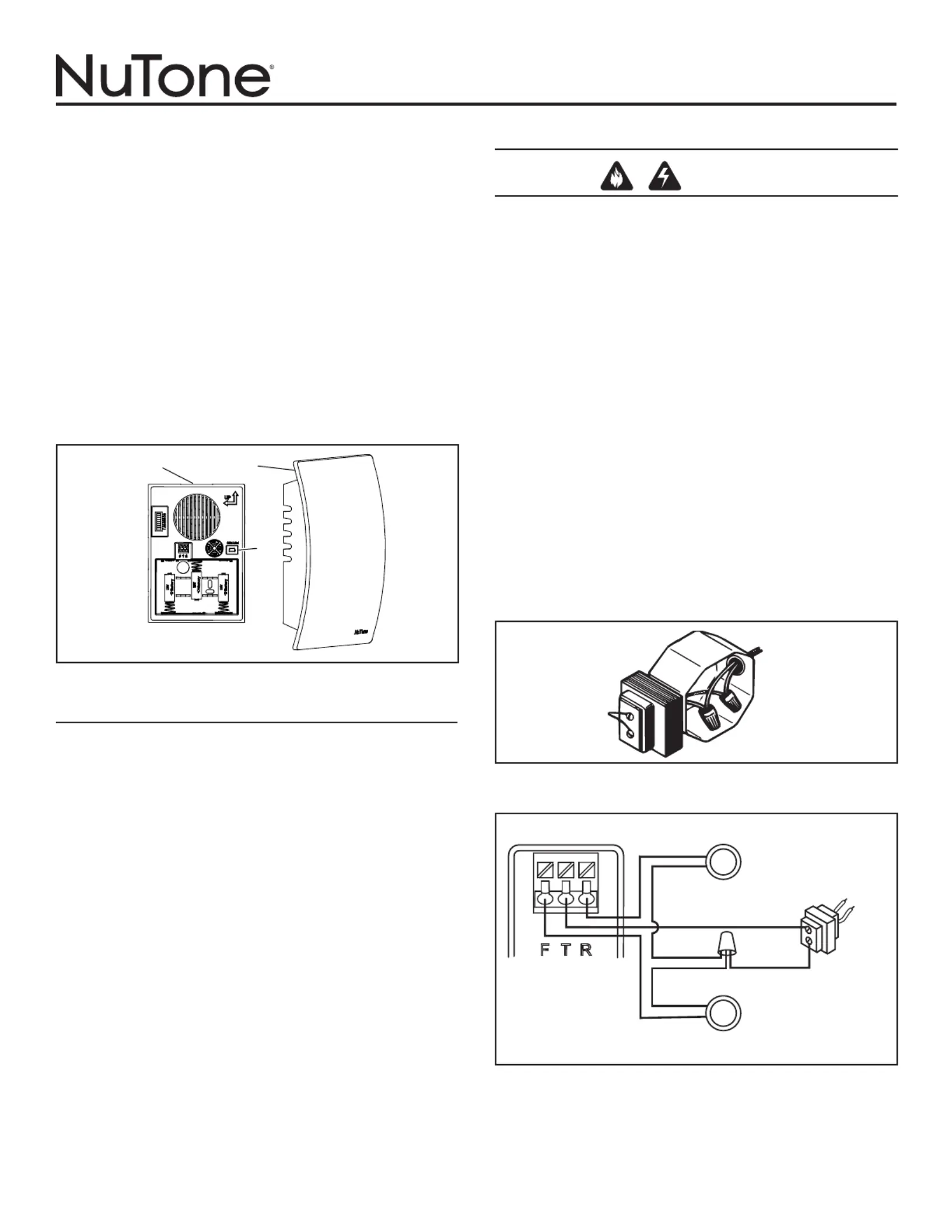
1. Remove chime cover (B) from chime base (A). You may need to
insert a finger into the large hole on the back of the chime base.
(Figure 1)
UPLOAD MP3 TUNES
1. Insert a USB Mini cable end into the doorbell mechanism USB jack
(C). (Figure 1)
2. Insert the remaining larger USB cable end into a USB port on your
computer.
3. On your WINDOWS computer,
Select “Start” in the bottom corner of your Desktop.
Select “My Computer”
Select the new device detected. (The drive “D:”, “E:”, etc. will vary
from computer to computer).
Select the device.
You will now see a window that contains several mp3 files. These
are the tunes that are pre-installed on your doorbell mechanism.
Search your computer for other mp3 songs that you wish to play
on your doorbell mechanism when activated. Note: Files must be
in mp3 format.
Once you have located those files, simply “COPY” the file and
“PASTE” it into the folder that contains the pre-installed doorbell
files.
Confirm that the transfered files are complete.
4. Remove USB cable and proceed to one of the following sections.
INSTALLATION & OPERATING INSTRUCTIONS
READ AND SAVE THESE INSTRUCTIONS
WIRES
TO
CHIME
SUPPLY
WIRE
FIGURE 2
FIGURE 3
WIRING DIAGRAM
SCREWLESS
WIRING CONNECTOR
ON CHIME BASE
REAR DOOR PUSHBUTTON
120 VAC
WIRING
TRANSFORMER
FRONT DOOR
PUSHBUTTON WITH
DIODE INSTALLED
A
B
C
FIGURE 1
NEW WIRED CHIME INSTALLATION
WARNING
TO REDUCE THE RISK OF FIRE, ELECTRIC SHOCK, OR INJURY TO
PERSONS, OBSERVE THE FOLLOWING:
Use this unit only in the manner intended by the manufacturer. If you have
questions, contact the manufacturer at the address or telephone number
listed in the warranty.
Before servicing or cleaning unit, switch power off at service panel and
lock the service disconnecting means to prevent power from being
switched on accidentally. When the service disconnecting means cannot
be locked, securely fasten a prominent warning device, such as a tag,
to the service panel.
Installation work and electrical wiring must be done by a qualified
person(s) in accordance with all applicable codes and standards, including
fire-rated construction codes and standards.
When cutting or drilling into wall or ceiling, do not damage electrical wiring
and other hidden utilities.
Use NuTone
®
16 volt transformer with a minimum rating of 10 VA (purchase
separately).
When stapling wires to studs or joists, do not allow staples to cut through
wire insulation.
1. Mount the transformer to a junction box (attic location is not
recommended) or circuit breaker box.
2. Connect house power leads to transformer leads: black to black,
white to white, ground to green. (Figure 2)
3. Route 2-conductor 18-22 gauge wire from the transformer screw termi-
nals and from the pushbutton terminals to the chime location. (Figure 3)
4. Label all wires at chime location in the following manner:
F – Front Pushbutton Wire
TTransformer Wire
R – Rear Pushbutton Wire (if installed)
2
5. The chime can be installed vertically or horizontally. Determine your
preferred orientation. Locate the arrows on the front of the chime
base. Make sure one of the arrows is pointing up. (Figure 4)
6. Bring wires through the circular wire hole (D) in chime base. (Figure
4)
7. Mount chime base to wall using screws provided. Always use 2
screws for wall mounting. (Figure 4)
8. Connect wires to the screwless wiring connector as follows: Wire “F”
to connector terminal “F”, wire “T” to connector terminal “T” and wire
“R” to connector terminal “R” if installed. (Figure 3)
9. Proceed to section titled: “INSTALL WIRED PUSHBUTTON”.
EXISTING WIRED CHIME INSTALLATION
TURN OFF POWER AT SERVICE ENTRANCE.
1. Verify a 16-volt transformer with a minimum rating of 10 VA is in-
stalled.
2. Remove existing chime cover.
3. Label all wires in the following manner:
F – Front Pushbutton Wire
TTransformer Wire
R – Rear Pushbutton Wire (if installed)
4. Disconnect all wires from existing chime base and remove from wall.
5. Follow Steps 6 through 9 under section titled: “NEW WIRED
INSTALLATION.
FIGURE 5
DIODE FOR FRONT DOOR
PUSHBUTTON
FIGURE 6
WRAP
DIODE WIRE
AROUND
EACH
TERMINAL
SCREW
AND CLIP
EXCESS
WIRES
DIODE
SILVER BAND
RECESSED FRONT
DOOR PUSHBUTTON
SURFACE-MOUNT FRONT
DOOR PUSHBUTTON
TRANSFORMER
WIRE
FRONT
WIRE
INSTALL WIRED PUSHBUTTONS
Power to transformer should be disconnected during pushbutton
installation.
A diode must be added to the front door pushbutton so that power
will be supplied continuously to the chime.
Do not install a diode on the rear door pushbutton.
1. Locate the envelope containing the front door pushbutton diode.
(Figure 5)
2. If using an existing pushbutton(s), remove existing pushbutton(s)
from wall. If installing new pushbutton(s), refer to installation
instructions provided with pushbutton(s).
3. Gently loosen pushbutton terminal screws and install diode from Step
1 on front door pushbutton only. (Figure 5) Wrap diode wires around
terminals and clip excess wires. (Figure 6)
4. Connect the chime wire to the front door pushbutton terminal closest to
the silver band on the diode. Connect the transformer wire to the other
terminal.
5. Restore power to transformer.
6.
Press the pushbutton and listen for the chime to sound. If chime does
not operate, disconnect power to transformer and reverse orientation of
diode. Restore power to transformer.
7. After confirming chime operates, follow steps under section titled
“Manage Chime Notification to select a tune, set tune duration, and
set volume.
8. Install pushbutton(s) on wall.
NOTE: To prevent shorting on metal siding, place a piece of
insulating tape on the siding surface near the diode.
NOTE: Lighted pushbutton brightness will be reduced by 30%-40%.
This is normal and will increase the life of the bulb.
9. Place cover (B) over chime base (A) and press down to install.
A “click” will confirm that it is securely attached. (Figure 1)
10. Proceed to section titled: “Manage Chime Notifications”.
D
FIGURE 4
VERTICAL
MOUNTING
HOLES
HORIZONTAL
MOUNTING
HOLES
3
WIRELESS CHIME INSTALLATION
Unobstructed wireless operating range: Up to 100 feet.
NOTE: Wireless pushbutton sold separately. Refer to installation
instructions included with wireless pushbutton.
Keep batteries out of the reach of children.
1. Insert three alkaline “D” batteries (not included) (E) in battery com-
partment. Make sure batteries are oriented properly. (Figure 7)
2. Obtain wireless pushbutton(s) (sold separately) and install battery
per wireless pushbutton(s) instructions.
3. Press pushbutton(s) to confirm the chime mechanism and
pushbutton(s) work properly. If the chime does not sound:
a. Confirm the code settings in the chime mechanism and wireless
pushbutton(s) are the same. Jumpers (F) installed on the num-
bered contacts on the chime mechanism must match the switches
or jumpers in the wireless pushbutton(s). (Figures 7 & 8)
E
F
FIGURE 7
123456
ON
7 8
SWITCHES 2, 4, 6
IN OFF POSITION
JUMPERS REMOVED (OFF)
FROM 2, 4, 6
b. Verify proper installation of batteries in chime mechanism and
pushbutton(s).
c. Check condition of batteries in chime mechanism and
pushbutton(s). Replace if required.
4. After confirming chime operates, follow steps under section titled
“Manage Chime Notification” before proceeding to Step 5.
5. If more than one pushbutton is being installed, refer to Figure 9 to
assign doors.
6. Install the wireless pushbutton(s) at the desired door(s). Refer to
installation instructions provided with wireless pushbutton(s).
7. Place chime mechanism in desired location. Confirm operation by
pressing pushbutton(s). If the chime does not sound:
a. The chime or pushbutton(s) are mounted on or near stucco or
metal studs, the transmitter range may be reduced. Use wood
shims to raise chime or pushbutton(s) 1/4” to 1/2” from surface.
b. Concrete floors and walls may also reduce transmitter range.
Move chime away from concrete floor or wall.
c. Install chime mechanism closer to wireless pushbutton(s).
8. Remove batteries from mechanism.
9. Mount chime base to wall using screws provided (see Step 8 in “New
Wired Chime Installation” section).
10. After mounting chime base to wall, install batteries.
11. Place cover (B) over chime base (A) and press down to install.
A “click” will confirm that it is securely attached. (Figure 1).
12. Proceed to section titled: “Manage Chime Notification.
PUSH
BUTTON
BATTERY
{
CODE SET
JUMPERS 1-6
CODE SET
SWITCHES 1-6
{
WIRELESS PUSHBUTTON - EXAMPLE CODE SETTING
(Pushbutton will have jumpers or switches)
WIRELESS CHIME - EXAMPLE CODE SETTING
JUMPERS REMOVED (OFF)
FROM 2, 4, 6
WIRELESS
CHIME
JUMPERS
{
FIGURE 8
1 8
JUMPERS
{
WIRELESS PUSHBUTTON - ASSIGN DOORS
(Wireless pushbutton will have jumpers or switches)
PUSH
BUTTON
BATTERY
{
DOOR SET
JUMPERS
*,X,Y
DOOR SET
SWITCH 8
123456
ON
7 8
123456
ON
7 8
SWITCH 8 ON
SWITCH 8 OFF
FIGURE 9
OR
FRONT
DOOR
REAR
DOOR
FRONT
DOOR
REAR
DOOR
1 8

Produktspecifikationer

Varumärke: NuTone
Kategori: dörrklocka
Modell: LA600WH

Behöver du hjälp?

Om du behöver hjälp med NuTone LA600WH ställ en fråga nedan och andra användare kommer att svara dig