Optex OA-72C Bruksanvisning
Optex dörr-/fönstersensor OA-72C
Läs gratis den bruksanvisning för Optex OA-72C (1 sidor) i kategorin dörr-/fönstersensor. Guiden har ansetts hjälpsam av 24 personer och har ett genomsnittsbetyg på 4.9 stjärnor baserat på 6 recensioner. Har du en fråga om Optex OA-72C eller vill du ställa frågor till andra användare av produkten? Ställ en fråga
Sida 1/1
SPECIFICATIONS
Model
Cover color
Mounting height
Detection area
Detection method
Depth angle adjustment
Width angle adjustment
Power supply
Power consumption
Operation LED
: OA-72C
: Silver
: 2.0 (6'7") to 4.0m (13'1")
: See DETECTION AREA
: Active Infrared Reflection
: -15° to +10°
: -10° to +10°
: 12 to 24VAC (±10%)
12 to 30VDC (±10%)
: < 1.5W (< 5VA at AC)
: Green / Stand-by
Red / 1st row detection
Orange / 2nd to 5th rows detection
Output
Output hold time
Response time
Operating temperature
Weight
Accessories
: Form C relay
50V 0.3A max.(resistance load)
: Approx. 0.5sec.
: < 0.3sec.
: -20°C to +55°C (-4°F to 131°F)
: 320g (11.2oz)
: 1 Cable 3m (9'10")
1 Operation manual
1 Mounting template
OUTER DIMENSIONS AND PART NAMES
OA-72C
5919373 OCT 2017
MANUFACTURER'S STATEMENT
Do not wash, disassemble, rebuild or repair the sensor, otherwise it may cause
electric shock or breakdown of the equipment.
Danger of electric shock
WARNING
CAUTION
NOTE
Disregard of the warning symbol can cause improper operation which may cause death
or serious injury.
Special attention is required to the section of this symbol.
Disregard of the caution symbol can cause improper operation which may cause injury of a
person or damage the object.
Read this operation manual carefully before use to ensure proper operation of this product.
Failure to read this operation manual may cause improper operation and may result in serious injury or death of a person.
The meanings of the symbols are as follows.
1. This product is a non-contact switch intended for ceiling mount for use on automatic sliding doors.
Do not use for any other applications.
2. When setting the sensors detection area, make sure that there is no traffic around the installation site.
3. Before turning the power ON, check the wiring to prevent damage or malfunction of equipment connected
to the product.
4. Only use the product as specified in the operation manual provided.
5. Be sure to install and adjust the sensor in accordance with the local laws and standards of the country in
which the product is installed.
6. Before leaving the installation site make sure that the product is operating properly and instruct the building
owner/operator on proper operation of the door and the product.
7.The product settings can only be changed by an installer or service engineer. When changed, the
changed settings and the date shall be registered in the maintenance logbook accompanying the door.
The following conditions are not suitable for sensor installation.
-Fog or exhaust emission around the door
-Wet floor
-Vibrating header or mounting surface
-Moving objects, steel plate, emergency lights or illumination in the detection area or in vicinity
-Highly reflecting floor or highly reflecting objects around the door
(1) Mounting clips
(2) Connector
(7) Dipswitches
DETECTION AREA
[m(feet,inch)]
Sensor setting
Depth angle adjustment : 0°
: Emitting spots
: Emitting spots (can be eliminated)
*The values of the chart above is of the emitting spots, but not of the detection area.
(3) Cover
(4) Depth adjustment screw
(5) Width adjustment screw
(6) Operation indicator
mm(inch)
A
B
C
D
E
2.20
(7'3")
0.13
(5.1")
0.37
(1'3")
0.63
(2'1")
0.93
(3'1")
1.24
(4'1")
2.50
(8'2")
0.15
(5.9")
0.43
(1'5")
0.72
(2'4")
1.06
(3'6")
1.41
(4'8")
F
G
1.08
(3'7")
1.65
(5'5")
1.24
(4'1")
1.88
(6'2")
H
2.25
(7'5")
2.57
(8'5")
3.00
(9'10")
0.18
(7.1")
0.51
(1'8")
0.87
(2'10")
1.28
(4'2")
1.70
(5'7")
3.50
(11'6")
0.21
(8.3")
0.60
(1'12")
1.01
(3'4")
1.49
(4' 11")
1.98
(6'6")
1.48
(4'10")
2.25
(7'5")
1.73
(5'8")
2.63
(8'8")
3.08
(10'1")
3.59
(11'9")
4.00
(13'1")
0.24
(9.4")
0.69
(2'3")
1.16
(3'10")
1.71
(5'7")
2.26
(7'5")
1.98
(6'6")
3.00
(9'10")
4.10
(13'5")
I
(7)
(6)(4)
(5)
(1)
(2)
(3)
main unit
155(6 2/16")
13(1/2")
58(2 5/16")
125(4 15/16")
1
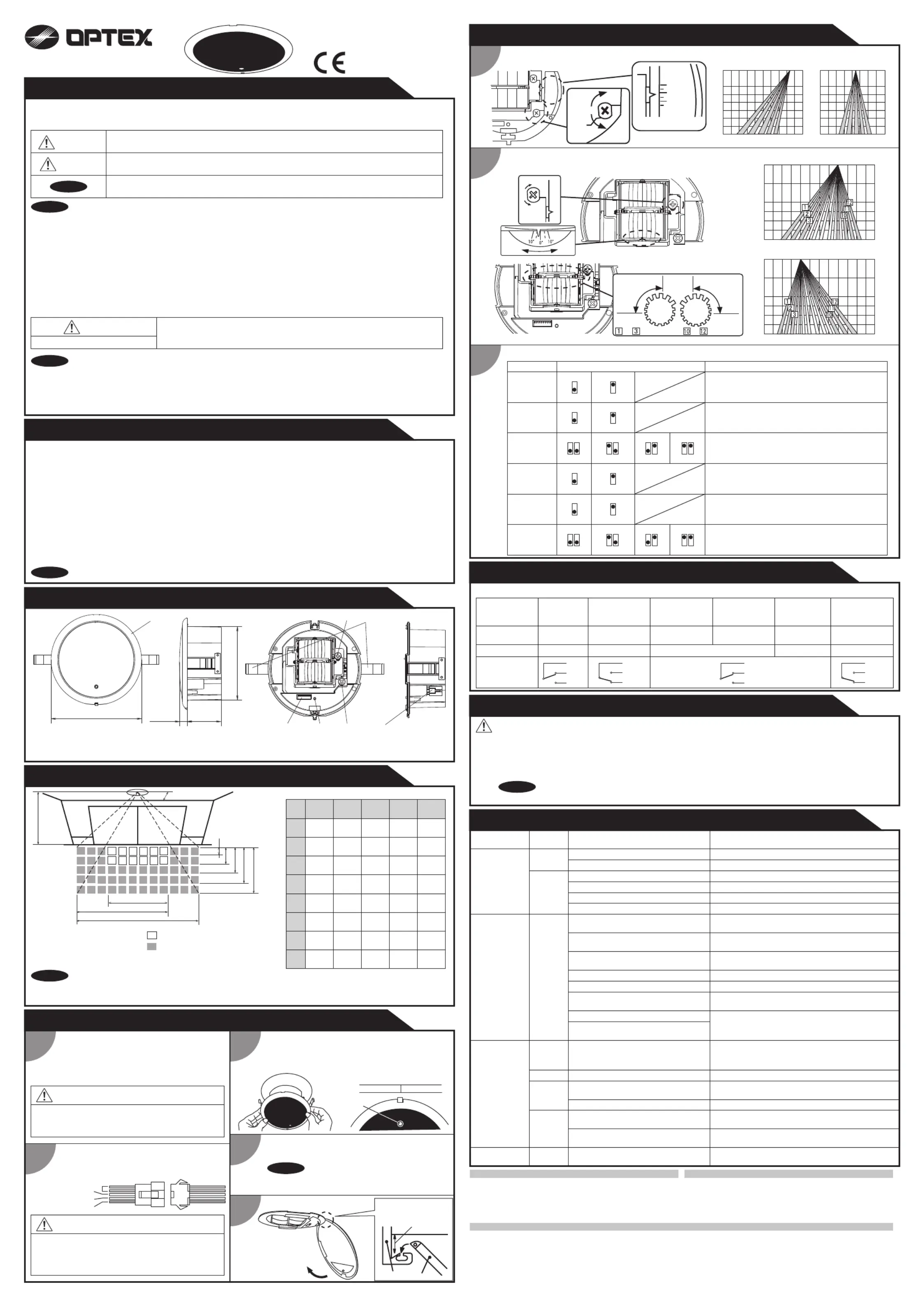
ADJUSTMENTS
Area depth angle adjustment
-15° to the door side
Door Side
Deep
Shallow
Depth angle scale
+10°
-10°
-15°
10° to the outside
2.0m
3.0m
4.0m
2.0m
3.0m
4.0m
4.0m3.0m2.0m1.0m02.0m1.0m-1.0m0
1st row
2nd row
3rd row
4th row
5th row
B
C
D
E
F
G
H
I
A
300mm(11.8")
Wrong wiring or connection failure.Check the wires and connector.
Wrong wiring or connection failure.Check the wires and connector.
Sensitivity is too high.Set the sensitivity lower.
Remove the objects.
Adjust the detection area to "deep" (outside).
Problem
Operation
LED
Possible cause Possible countermeasures
NonePower supply voltage.Set to the stated voltage.
Wrong wiring or connection failure.
Signal saturation.
Sensor failure.
The detection area overlaps with
the door / header.
Adjust the detection area to "deep" (outside).
Contact your installer or service engineer.
Door opens
when no one
is in the
detection area.
(Ghosting)
UnstableThe detection area overlaps with that of
another sensor.
The detection area overlaps with the
door / header.
Reflecting objects in the detection area.
Or reflecting light on the floor.
Door remains
open
Red
or
Orange
Sudden change in the detection area.Check .ADJUSTMENTS 3
If the problem still persists, hard-reset the sensor.
(turn the power OFF and ON again.)
Slow
Green
blinking
Fast
Green
blinking
Check the wires and connector.
Remove highly reflecting objects from the detection
area or lower the sensitivity or change the area angle.
Sensitivity is too low.Set AIR area width to "Wide".
Wipe the detection window with a damp cloth.
Check ADJUSTMENTS 3.
Door does not
open when a
person enters
the detection
area.
Unstable
Door remains
closed
Proper
Proper
Dirty detection window.Wipe the detection window with a damp cloth.
It snows. Set the snow mode to ON.
Remove the objects.
Wet floor.Check the installation condition referring to
MANUFACTURE’S STATEMENT on the reverse
side.
The exhaust emission or fog penetrate
into the detection area.
Objects that move or emit light in the
detection area.
Wrong detection area positioning.
Sensitivity is too low.
Short presence detection timer.
Check ADJUSTMENTS 1 & 2.
Set the sensitivity higher.
Set the presence detection timer longer.
TROUBLESHOOTING
The specifications herein are subject to change without prior notice due to improvements.
The actual detection area may become smaller depending on the ambient light, the color / material of the
object or the floor as well as the entry speed of the object.
OPTEX CO., LTD.
Manufacturer
5-8-12 Ogoto Otsu 520-0101, Japan
TEL.: +81(0)77 579 8700 FAX.: +81(0)77 579 7030
WEBSITE: www.optex.net
OPTEX Technologies B.V.
European Subsidiary
Henricuskade 17, 2497 NB The Hague, The Netherlands
TEL.: +31(0)70 419 41 00 FAX.: +31(0)70 317 73 21
E-MAIL: [email protected] WEBSITE: www.optex.eu
East coast office
8510 McAlpines Park Drive, Suite 108
Charlotte, NC 28211 U.S.A.
TEL.: +1-800-877-6656 FAX.: +1(704)365-0818
WEBSITE: www.ot-inc.com
OPTEX INCORPORATED
North and South America Subsidiary
18730 S. Wilmington Avenue, Suite 100 Rancho
Dominguez CA 90220 U.S.A
TEL.: +1-800-877-6656 FAX.: +1(310)898-1098
WEBSITE: www.ot-inc.com
NOTE
WARNING
NOTE
NOTE
NOTE
1
2
3
4
INSTALLATION
5
1. Affix the mounting template at the desired
mounting position.
2. Drill a mounting hole.
(recommended diameter : ø130mm (5"))
3. Remove the mounting template.
Risk of getting caught
Supply power to the sensor. Adjust the detection area
and set the dipswitches. (See )ADJUSTMENTS
Before starting the procedure, ensure that the power
is turned OFF. When passing through the cable to the
hole, make sure not to tear the shield, otherwise it
may cause electric shock or breakdown of the sensor.
Danger of electric shock
To enable the presence detection, do not
enter the detection area for 10 seconds
after supplying the power.
Remove the cover from the sensor.
Plug the connector of the cable to the connector
of the sensor.
Main unit
Cover
1. Install the sensor with cover, keeping the direction
of operation indicator towards the door.
2. Press the mounting clips against the sensor to
place the sensor into the mounting hole.
Mount the cover on the sensor.
Door
Operation
indicator
Make sure that the deteciton window faces the floor
surface. When it faces the wall or the ceiling, the
sensor may not operate properly.
Mount the cover by making
a small gap between sensor
and ceiling.
CAUTION
Grey : Power supply
White : COM.
Yellow : N.O.
Green : N.C.
WARNING
NOTE
3
2
Width detection area adjustment
Dipswich setting
Left
Right
RightLeft
2.0m
3.0m
4.0m
4.0m3.0m2.0m2.0m1.0m1.0m0
2.0m
3.0m
4.0m
4.0m3.0m2.0m1.0m01.0m2.0m
10° to left
10° to right
WideWide
NarrowNarrow
to eliminationto elimination
Area
adjustment
2 rows3 rows4 rows5 rows
Snow mode
FunctionSetting
Comment
Presence
timer
Frequency
1st and 2nd rows include presence detection
function.
11
LowHigh
Sensitivity
Set the sensitivity according to the mounting height.
Adjust the sensitivity according to your risk
assessment.
22
2 to 3m2.7 to 4m
Mounting
height
5
Setting1
5
Setting2
OFF
6
ON
6
Set the sensitivity according to the mounting height.
Adjust the sensitivity according to your risk
assessment.
30sec.
43
60sec.
43
180sec.
43
600sec.
43
87878787
When using more than one sensor close to each
other, set the frequency different for each sensor.
Set this switch to ON if the sensor is used in a
region with snow or a lot of insects.
Adjust the area detection depth by selecting the
dipswitches.
CHECKING
Check the operation according to the chart below.
Status
GreenGreen
Motion
detection active
Red
Motion/Presence
detection active
Entry
Outside of
detection area
Outside of
detection area
Entry into 3rd,
4th or 5th row
Entry into
2nd row
Entry into
1st row
Orange
Stand-byStand-by
Operation LED
Output
Presence
detection
Power OFF
-
None
COM
N.O.
N.C.
COM
N.O.
N.C.
COM
N.O.
N.C.
COM
N.O.
N.C.
1. Wipe the detection window with a damp cloth. Do not use any cleaner or solvent.
2. Do not wash the sensor with water.
3. Do not disassemble, rebuild or repair the sensor yourself, otherwise an electric shock may occur.
4. When an operation LED blinks green, contact your installer or service engineer.
5. Always contact your installer or service engineer when changing the settings.
6. Do not paint the detection window.
1. When turning the power ON, always walk-test the detection area to ensure proper operation.
2. Do not place any objects that move or emit light in the detection area. (e.g. plant, illumination, etc.)
INFORM BUILDING OWNER / OPERATOR OF THE FOLLOWING ITEMES
WARNING
NOTE
Produktspecifikationer
| Varumärke: | Optex |
| Kategori: | dörr-/fönstersensor |
| Modell: | OA-72C |
Behöver du hjälp?
Om du behöver hjälp med Optex OA-72C ställ en fråga nedan och andra användare kommer att svara dig
dörr-/fönstersensor Optex Manualer

5 September 2025
5 September 2025
4 September 2025
3 September 2025
3 September 2025
3 September 2025
3 September 2025
3 September 2025
dörr-/fönstersensor Manualer
Nyaste dörr-/fönstersensor Manualer
19 September 2025
10 September 2025
10 Augusti 2025
29 Juli 2025
27 Juli 2025
10 Juli 2025