Optex VXI-ST Bruksanvisning


Läs gratis den bruksanvisning för Optex VXI-ST (3 sidor) i kategorin Rörelsedetektorer. Guiden har ansetts hjälpsam av 21 personer och har ett genomsnittsbetyg på 4.4 stjärnor baserat på 11 recensioner. Har du en fråga om Optex VXI-ST eller vill du ställa frågor till andra användare av produkten? Ställ en fråga

Sida 1/3
No. 59-1935-1
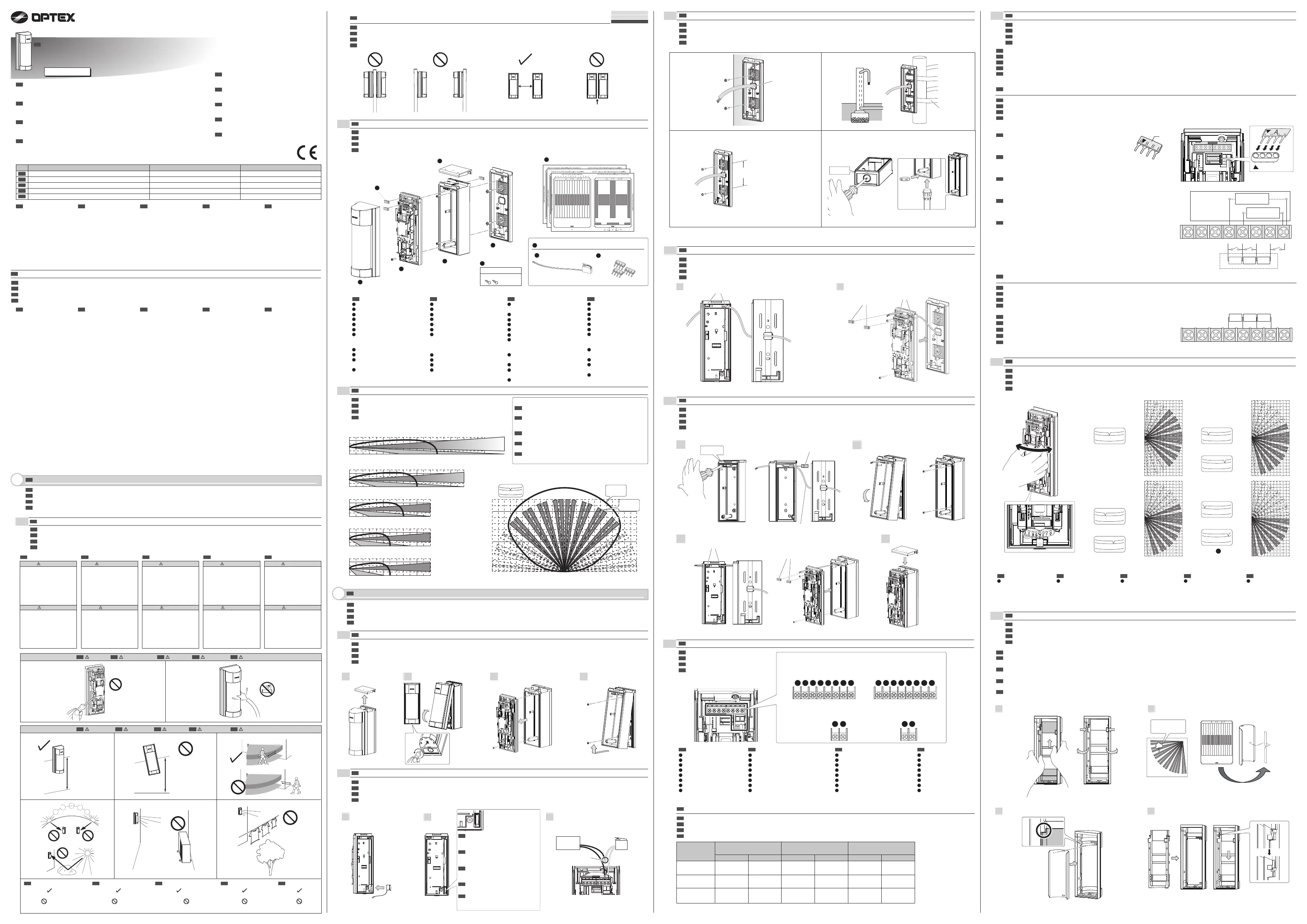
MULTI DIMENSIONAL OUTDOOR DETECTOR
VX Infinity
TM
series
VX Infinity
TM
series
FEATURES
WIRED MODEL
2-3
MOUNTING
EN
2-4
MOUNTING WITHOUT BACK BOX
EN
2-5
MOUNTING WITH BACK BOX
EN
1
1 2
2
3 4
2-7
PLUG-IN END OF LINE RESISTORS (EOL) (OPTION)
EN
-When setting the resistance value using PLUG-IN EOL
Three types of signals - ALARM, TROUBLE, and
TAMPER - can be recognized through the
combination of the resistance value and wires for
the TR, COM, and TP terminals.
-When setting the resistance value without using PLUG-IN EOL
Wire resistors between the appropriate terminals as follows:
This feature may be used when connecting VXI to a control panel that supports the EOL technique.
+ - SP TR COM AL TP TP
2-8
AREA ANGLE ADJUSTMENT
EN
2-9
AREA MASKING
EN
1
2
3 4
INSTALLATION INSTRUCTIONS
INSTRUCTIONS D'INSTALLATION
DETECTEUR D'EXTERIEUR MULTIDIMENTONNEL
Série VX Infinity
TM
MODÈLE FILAIRE
INSTALLATIONSANWEISUNGEN
ISTRUZIONI D’INSTALLAZIONE
MANUAL DE INSTALACIÓN
EN
The VX Infinity
TM
series
provide highly reliable
detection functions,
reducing false reports or
report losses. The VX
Infinity
TM
series deliver
stable detection
performance even in
severe outdoor
environments.
EN
EN
EN
EN
La série VX Infinity
TM
offre
des fonctions de détection
très fiables, ce qui réduit
les erreurs ou les pertes de
rapports. La série VX
Infinity
TM
offre des
performances de détection
stable, même dans un
environnement extérieur
difficile.
FR
FR
Die VX Infinity
TM
Serie
bietet höchst zuverlässige
Wahrnehmungsfunktionen
und reduziert
Falschmeldungen oder
Meldungsverluste. Die VX
Infinity
TM
Serie liefert stabile
Wahrnehmungsleistungen,
sogar in den schwierigsten
Außenumgebungen.
DE
DE
I modelli della serie VX
Infinity
TM
sono molto
affidabili e riducono sia
i falsi sia i mancati
rilevamenti. La loro
capacità di rilevamento
inoltre rimane stabile
anche in condizioni
ambientali esterne critiche.
IT
IT
La serie VX Infinity
TM
ofrece funciones de
detección de alta fiabilidad,
reduciendo así falsas
alarmas y la pérdida de
detecciones potencialmente
peligrosas. La serie VX
Infinity
TM
proporciona una
detección estable incluso
en condiciones
medioambientales adversas.
ES
ES
FR
DE
IT
ES
MULTIDIMENSIONALER AUSSEN-DETEKTOR
RILEVATORE MULTIDIMENSIONALE PER ESTERNI
MODELLO CABLATO
DETECTOR DE MOVIMIENTO PARA EXTERIORES
MODELO CON CABLE
VXI-ST VXI-AM
VXI-ST with anti-masking
VXI-DAM
VXI-AM with micro-wave
VXI-ST avec anti-masquage VXI-AM avec micro-ondes
VXI-ST mit Anti-Maskierung VXI-AM mit Mikrowellen
VXI-ST con funzione antimascheramento
VXI-AM con sensore a microonde
Standard model with 2 PIR
Modèle standard avec 2 PIR
Standardmodell mit 2 PIR
Modello standard con due sensori all’infrarosso passivo
Modelo estándar con 2 sensores de infrarrojos (PIR)
VXI-ST con antienmascaramiento VXI-AM con micro-ondas
%$6,&)($785(6
- 12 m (40 ft.) by 90 degree
flexible detection pattern
adjustable to 5 ranges
- SMDA Logic for
advanced temperature
compensation and
environmental noise
immunity.
- Easy Masking for over
spill prevention
- Double Conductive
Shielding against bright
light disturbance.
- Conduit/TX-Battery Case
for both wired and
wireless-ready models.
237,21$/)($785(6
- Active IR Anti-Masking for
detecting covering objects
- Tough Mod Dual
Technology based on
OPTEX gold-plated
microwave module
&$5$&7(5,67,48(6
'(%$6(
- 12 m (40 ft) avec modèle
de détection flexible et
réglable à 90 degrés et
il y a 5 options.
- SDMA logic pour
compensation avancée de
température et immunité
aux bruits de
l'environnement.
- Masquage facile pour
empecher la divulgation
dans certaines zones.
- Double blindage
conducteur contre les
perturbations de lumière.
- Boîtier Conduit/batterieTX
pour les deux modèles
filaires et sans fil.
&$5$&7(5,67,48(6
(1237,21
- IR active anti-masquage
pour détecter les objets
dissimulés
- Technologie robuste à
double Mode basée sur le
module
micro-ondes
OPTEX plaqué or.
FR
*581')81.7,21(1
- 12 m bei 90 Grad flexiblem
Wahrnehmungsmuster,
anpassbar an die 5
Reichweiten.
- SMDA-Logik für
fortgeschrittene
Temperaturkompensation
und
Umgebungsgeräuschimmunität.
- Einfache Maskierung zur
Vermeidung von
Störungen.
- Doppelte
Leitungsabschirmung
gegen helle
Lichtstörungen.
- Stromnetz-/
TX-Batteriegehäuse
geeignet für Batterie- als
auch festangeschlossene
Modelle.

237,21$/()81.7,21(1
- Aktive IR Anti-Maskierung
zur Wahrnehmung von
verborgenen Objekten
- Tough Mod Dual
Technologie basierend auf
OPTEX goldbeschichteten
Mikrowellen-Modulen
DE IT
ES
EN
INTRODUCTION
INTRODUCTION
1
1-1
BEFORE INSTALLATION
EN
FR
EINLEITUNG
DE
INTRODUZIONE
IT
INTRODUCCIÓN
ES
CARACTERISTIQUES
FUNKTIONEN
CARATTERISTICHE
CARACTERÍSTICAS
AVANT L'INSTALLATION
FR
VOR DER INSTALLATION
DE
PRIMA DELL’INSTALLAZIONE
IT
ANTES DE LA INSTALACIÓN
ES
EN
FR DE IT ES
The check mark indicates
recommendation.
The nix sign indicates
prohibition.
EN
La marque indique une
recommandation.
Le signe nix indique
une interdiction.
FR
Die Prüfe Markierung
zeigt eine Empfehlung an.
Die Vermeide Markierung
zeigt ein Verbot an.
DE
Il simbolo indica una
raccomandazione.
Il simbolo indica un
divieto.
IT ES
El signo indica
Recomendación
El signo indica
Prohibición
Attenzione
Avvertenza
Questo simbolo segnala
una situazione che
comporta il rischio di
lesioni gravi o fatali
in caso d’inosservanza
delle istruzioni fornite o di
uso improprio del prodotto.
Questo simbolo segnala
una situazione che
comporta il rischio di lesioni
e/o danni alle cose in caso
d’inosservanza delle
istruzioni fornite o di uso
improprio del prodotto.
Warning
Caution
Failure to follow the
instructions provided with
this indication and
improper handling may
cause death or serious
injury.
Failure to follow the
instructions provided with
this indication and
improper handling may
cause injury and/or
property damage.
Avertissement
Attention
Ne pas suivre les
instructions fournies avec
ces instructions
et une mauvaise
manipulation peut causer
des blessures graves
voire mortelles.
Ne pas suivre les
instructions fournies avec
ces instructions
et une mauvaise
manipulation peut causer
des blessures graves et/ou
des dommages matériels.
Warnung
Vorsicht
Fehler in der Befolgung
dieser Anleitung und
unangemessene
Behandlung des Gerätes
können zum Tod oder zu
schweren Verletzungen
führen.
Fehler in der Befolgung
dieser Anleitung und
unangemessene
Behandlung des Gerätes
können zu Verletzungen
oder Beschädigungen
des Gerätes führen.
Advertencia
Precaución
Respete las instrucciones
de seguridad indicadas
con este símbolo para
prevenir serios daños o
incluso la muerte.
Siga las instrucciones
indicadas con este
símbolo para prevenir
posibles heridas o daños
materiales.
0.8 – 1.2 m
(2.64 – 3.94 ft)
Warning
EN
Avertissement
FR
Warnung
DE
Attenzione
IT
Advertencia
ES
-Precautions for installing two or more sensors when using micro-wave model
VXI-ST
VXI-AM
VXI-DAM
EN
EN
1-2
PARTS IDENTIFICATION
EN
1-3
DETECTION AREA
EN
INSTALLATION
2
2-1
BEFORE MOUNTING
1 2 4
EN
2-6
WIRING
EN
A
%
&
D
E
)
*
H
A
%
&
D
E
)
*
H
FR
Alimentation (+)
Alimentation (-)
Pièce détachée
Alarme
Autoprotection
Aux entrée
Problème
Commun
DE
A
%
&
D
E
)
*
H
Stromanschluss (+)
Stromanschluss (-)
Frei
Alarme
Schiene
Aux-Eingang
Trouble
Gewöhnlich
IT
A
%
&
D
E
)
*
H
Alimentazione (+)
Alimentazione (-)
Riserva
Allarmi
Antimanomissione
Ingr. ausil.
Pericolo
Comune
ES
A
%
&
D
E
)
*
H
Entrada (+)
Entrada (-)
Libres (No user)
Alarma
Tamper
Entrada auxiliar
Problema
Común
EN
The detection area
becomes
14 zones only when
A or G is selected.
EN
A
FR
A
La zone de détection
ne couvre plus que 14
zones si l'on
sélectionne A ou G.
DE
A
Der Prüfungsbereich
besteht aus 14 Zonen,
aber es A oder G
auswählen kann.
IT
A
L’area di rilevamento
diventa a 16 zone solo
quando A o G sono
selezionati.
ES
A
El área de detección
pasa a 14 zonas solo
cuando se selecciona
A o G.
EN
EN
EN
Trois types de signaux - ALARME, PANNE, et
AUTO PROTECTION - peut être reconnue par la
combinaison de la valeur des résistances et des
fils pour TR, COM, et les bornes TP.
Drei Signaltypen -ALARM, TROUBLE und
MANIPULATION- können durch Kombination der
Widerstandswerte und Kabel für TR-, COM- und
TP-Terminale erkannt werden.
Combinando il valore di resistenza e i conduttori
dei morsetti TR, COM e TP il rilevatore può
riconoscere tre tipi di segnale: ALLARME,
PERICOLO e ANTIMANOMISSIONE.
Puede haber tres tipos de señales –ALARMA.
PROBLEMA Y DISPOSITIVO SEGURIDAD
(ALARM, TROBLE, TAMPER) reconocidas en la
combinación de los valores de las resistencias y
de los cables para las terminales TR, CON y TP.
EN
EN
Résistances de fil entre les bornes appropriées comme suit:
Kabelwiderstände zwischen den angemessenen Terminals wie folgt:
Collegare nel seguente modo i resistori tra i morsetti pertinenti:
Las resistencias entre los terminales apropiados son de la siguiente manera:
FESTANGESCHLOSSENES MODELL
VX Infinity
TM
Serie
Serie VX Infinity
TM
Serie VX Infinity
TM
-Précautions à prendre pour l’ installation de deux ou plusieurs capteurs lors de l’ utilisation d’ un modèle de micro-ondes
FR
-Vorsorge für die Anbringung von zwei oder mehreren Sensoren bei Benutzung von Modellen mit Mikrowellen
DE
-Precauzioni per l'installazione di due o più sensori in caso di utilizzo del modello a microonde
IT
-Precauciones a la hora de instalar dos o más detectores al utilizar el modelo micro-ondas
ES
3
Wall tamper (option)
WRS-02
Control panel
Twist and swage
IDENTIFICATION DES PIECES
FR
TEILE-IDENTIFIKATION
DE
DESCRIZIONE DELLE PARTI
IT
IDENTIFICACIÓN DE LOS PARTES
ES
ZONE DE DETECTION
FR
WAHRNEHMUNGSBEREICH
DE
AREA DI RILEVAZIONE
IT
ÁREA DE DETECCIÓN
ES
EN
FR
DE
IT
ES
MONTAGE
FR
MONTAGE
DE
MONTAGGIO
IT
MONTAJE
ES
Wall mount
1.0 m (3.28 ft) or more Less than 1.0 m (3.28 ft)
Pole mount
Electric gang box mount Conduit
Metal band
(25 mm or less in width)
Pitch 83.5 mm (3.29 inch)
MONTER SANS BOITIER ARRIEREE
FR
MONTAGE OHNE RÜCKKASTEN
DE
MONTAGGIO SENZA SCATOLA POSTERIORE
IT
MONTAJE SIN CAJETÍN
ES
MONTAGE POUR BOITIER ARRIERE
FR
MONTAGE MIT RÜCKKASTEN
DE
MONTAGGIO CON SCATOLA POSTERIORE
IT
MONTAJE CON CAJETÍN
ES
CABLAGE
FR
VERKABELUNG
DE
COLLEGAMENTI
IT
CABLEADO
ES
-Lors du réglage de la valeur de résistance à l'aide de ENFICHABLE EOL
FR
-Beim Einstellen der Widerstandswerte unter Verwendung eines EOL-STECKERS
DE
-Impostazione del valore di resistenza in caso d'uso dei contatti di fine linea a innesto (EOL)
IT
-Cuando se ajusta el valor de la resistencia usando el PLUG-IN EOL
ES
FR
DE
IT
ES
EXTREMITE DE RACCORDEMENT DES RESISTANCES DE LIGNE (EOL) (OPTION)
FR
STECKER ENDWIDERSTÄNDE (EOL) (OPTION)
DE
RESISTORI DI FINE LINEA (EOL) A INNESTO (OPZIONE)
IT
RESISTENCIAS DE FIN DE LÍNEA (EOL) DE CONECTOR (OPCIÓN)
ES
Cette fonctionnalité peut être utilisée lors de la connexion VXI à un panneau de contrôle qui prend en charge la technique EOL.
FR
Diese Funktion kann benutzt werden, wenn VXI mit einem Steuerpult, das EOL-Technologie unterstützt, verbunden werden soll.
DE
Questa capacità permette di collegare il VXI a un pannello di controllo compatibile con la tecnica EOL (fine linea).
IT
Se puede usar está función cuando se conecte VXI a un panel de control que admita la técnica EOL.
ES
A
Type
COMMON
TROUBLE
ALARM
TAMPER
Triple-EOL
Double-EOL
TAMPER
ALARM
TROUBLE
TAMPER
ALARM
TROUBLE
PLUG-IN EOL
CONTROL PANEL
-Lors du réglage de la valeur de résistance à l'aide de ENFICHABLE EOL
FR
-Beim Einstellen der Widerstandswerte ohne EOL-STECKER
DE
-Impostazione del valore di resistenza in caso di non utilizzo di contatti di fine linea a innesto (EOL)
IT
-Cuando se ajusta el valor de la resistencia sin usar el PLUG-IN EOL
ES
FR
DE
IT
ES
REGLAGE DE LA ZONE ANGLE
FR
BEREICHSWINKELANPASSUNG
DE
REGOLAZIONE ANGOLARE DELLA ZONA DI RILEVAZIONE
IT
AJUSTE DEL ÁNGULO DEL ÁREA
ES
En cas d'objet non désiré au sein de la zone de détection, appliquer une étiquette de zone de masquage dans
la zone appropriée.
If there is an unwanted object within the detection area, apply an area masking label to the appropriate area.
FR
Falls sich ein unerwünschtes Objekt im Wahrnehmungsbereich befindet, bringen Sie ein Bereichsmaskierungsetikett
im betreffenden Bereich an.
DE
Per impedire il rilevamento indesiderato di corpi nella zona d’interesse occorre applicare le apposite etichette in corrispondenza
della direzione di tali corpi.
IT
Si hay algún objeto no deseado dentro del área de detección, coloque una máscara autoadhesiva en el área pertinente.
ES
ZONE DE MASQUAGE
FR
BEREICHSMASKIERUNG
DE
MASCHERAMENTO
IT
ÁREA DE ENMASCARAMIENTO
ES
-Power cable length
AWG22
(0.33mm
2
)
290 m
(950 ft)
620 m
(2,030 ft)
240 m
(790 ft)
520 m
(1,710 ft)
160 m
(520 ft)
360 m
(1,180 ft)
12 V
VXI-ST VXI-AM VXI-DAM
14 V 12 V 14 V 12 V 14 V
450 m
(1,480 ft)
980 m
(3,220 ft)
380 m
(1,250 ft)
820 m
(2,690 ft)
260 m
(850 ft)
560 m
(1,840 ft)
720 m
(2,360 ft)
1,570 m
(5,150 ft)
600 m
(1,970 ft)
1,310 m
(4,300 ft)
410 m
(1,350 ft)
900 m
(2,950 ft)
AWG20
(0.52mm
2
)
AWG18
(0.83mm
2
)
EN
Wire gauge
Current draw 20 mA Current draw 24 mA Current draw 35 mA
-Longueur du câble d'alimentation
FR
-Stromkabellänge
DE
-Lunghezza del cavo di alimentazione
IT
-Longitud del cable de alimentación
ES
a
b
c
d
e
f
g
h
i
j
l
m
n
k
PIR
MW
0
0
D
A
B
C
E
F
G
TOP VIEW
Area of horizontal position D
SIDE VIEW
Position 1 (Default)
Position 2
Position 3
Position 4
Position 5
1m
0
1m
0
1m
0
1m
0
1m
0
A
&
)
*
H
I
J
.
D
E
%
Couvercle du boîtier arrière
Eponge de câblage
Couvercle de l'appareil
Unité principale
Arrière du boiter
Plaque de montage
Jeu de vis
Pour montage mural
Vis (4 × 20 mm)
Joint masquage X 3 pcs
Accessoires en option
Autoprotection murale
(WRS-02)
BRANCHER SUR EOL (PEU)
FR
A
&
)
*
H
I
J
.
D
E
%
Rückkastendeckel
Drahtisolierung
Abdeckungseinheit
Haupteinheit
Rückkasten
Montageplatte
Schraubensatz
Zum an die Wand
montieren
Schraube
(4 × 20 mm)
Maskierungssiegel x 3 Teile
Optionale Ausstattung
Wandschiene (WRS-02)
EOL-STECKER (PEU)
DE
A
&
)
*
H
I
J
.
D
E
%
Coperchio della scatola
posteriore
Spugnetta di protezione cavo
Coperchio anteriore
Unità principale
Scatola posteriore
Base di fissaggio
Set di viti
Per montaggio a parete
Vite da 4 x 20 mm
Etichette di mascheramento
(3 pezzi)
Accessori opzionali
Dispositivo antimanomissione
da parete WRS-02
Fine linea (EOL) a innesto (PEU)
IT
A
&
)
*
H
I
J
.
D
E
%
Tapa del cajetín
Esponja para el cableado
Cubierta del cajetín
Unidad principal
Cajetín
Soporte de montaje
Tornillería
Para montaje en pared
Tornillo (4 × 20 mm)
Máscaras autoadhesivas
3 unidades
Accesorios opcionales
Antisabotaje para pared
(WRS-02)
Plug-in EOL (PEU)
ES
A
%
&
D
E
)
*
H
I
J
.
EN
FR
DE
IT
ES
3
AVANT D'EFFECTUER LE MONTAGE
FR
VOR DER MONTAGE
DE
PRIMA DELL’INSTALLAZIONE
IT
ANTES DE MONTARLO
ES
INSTALLATION
FR
INSTALLATION
DE
INSTALLAZIONE
IT
INSTALACIÓN
ES
Unwanted
object (Tree)
EN
2-2
WALL TAMPER WRS-02(OPTION)
AUTO PROTECTION MURALE WRS-02(OPTION)
FR
WANDSCHIENE WRS-02 (OPTION)
DE
DISPOSITIVO ANTIMANOMISSIONE WRS-02(OPZIONE)
IT
ANTISABOTAJE PARA PARED WRS-02(OPCIÓN)
ES
1
WRS-02 (option)
Back of the main unit
Knockout
Knockout
Position D
Position C
Position E
D
A
B
C
E
F
G
D
A
B
C
E
F
G
D
A
B
C
E
F
G
A
Position B
Position F
Position A
Position G
D
A
B
C
E
F
G
D
A
B
C
E
F
G
D
A
B
C
E
F
G
D
A
B
C
E
F
G
<VXI-ST> <VXI-AM> <VXI-DAM>
A % A %& &
&
D D DE E E E
)) ) )
* H
FR
DE
IT
ES
12m
(40 ft)
10m
(33.3 ft)
5m
(16.7 ft)
5m
(16.7ft)
10m
(33.3 ft)
12m
(40 ft)
The maximum detection length may vary as shown below
due to environment conditions.
La longueur maximale de détection peut varier comme
ci-dessous en raison des conditions thermiques de
l'environnement.
Die maximale Wahrnehmungslänge kann, wie unten
angezeigt, je nach Umweltbedingungen variieren.
La distanza massima di rilevamento può variare in base
alle condizioni ambientali come indicato di seguito.
La longitud máxima de detección puede variar, como se
indica debajo, debido a condiciones medioambientales.
ø 21 mm
Power (+)
Power (-)
Spare
Spare
Alarm
Alarm
Tamper
Tamper
Aux. input
Aux. input
Power (+)
Power (-)
Spare
Trouble
Common
Alarm
Tamper
Tamper
Aux. input
Aux. input
&$5$77(5,67,&+(',
%$6(
- Copertura di rilevazione
regolabile sino a 12 metri e
90°, programmabile in 5 livelli
- SMDA (Super Multi
Dimension Analysis),
logica avanzata di
compensazione della
temperatura e d’immunità
al rumore ambientale
-
Facilità di mascheramento
anticaduta
- Doppia schermatura
conduttiva contro i disturbi
dovuti a forte luce
- Involucro con condotto e
batterie TX sia per i
modelli a filo sia per quelli
senza filo
&$5$77(5,67,&+(
23=,21$/,
-
Funzione
antimascheramento
all’infrarosso attivo per il
rilevamento di
corpi/persone nascoste
- Tecnologia Tough Mod
Dual basata sul modulo a
microonde OPTEX con
placcatura in oro
&DUDFWHUtVWLFDV%iVLFDV
- 12 m (40 pies) por patrón
adjustable de detección
flexible de 90 grados hasta
5 rangos.
- Función lógica SMDA para
la compensación avanzada
de la temperatura y para
minimizar el ruido
medioambiental.
- Fácil enmascaramiento
para prevención de
derramamientos
- Doble Protección
Conductiva contra
perturbaciones de luz de
gran intensidad.
- Cubierta para el
Conducto/Batería-TX tanto
para los modelos con cable
como para los inalámbricos.
&DUDFWHUtVWLFDV
Opcionales
- Infrarrojos Activos
Antienmascaramiento para
detectar objetos escondidos
- Tecnología Dual Mod de
Altas Prestaciones basada
en el módulo de microondas
dorado de OPTEX
Optional accessories >>
Note >>
Caution
EN
Attention
FR
Vorsicht
DE
Avvertenza
IT
Precaución
ES
Cover unit
Main unit
Back box
Back box cap
Wiring sponge
Mounting plate
Masking seal × 3 pcs
For wall mounting
Screw kit
Screw (4 × 20 mm)
Wall tamper (WRS-02) PLUG-IN EOL (PEU)
5m
(16.7ft)
10m
(33.3 ft)
12m
(40 ft)
5m
(16.7ft)
10m
(33.3 ft)
12m
(40 ft)
5m
(16.7ft)
10m
(33.3 ft)
12m
(40 ft)
5m
(16.7ft)
10m
(33.3 ft)
12m
(40 ft)
5m
(16.7ft)
10m
(33.3 ft)
12m
(40 ft)
5m
(16.7ft)
10m
(33.3 ft)
12m
(40 ft)
2
Store the connecting cable in a
trench and seal with a label already in
place.
Rangez le câble de raccordement
dans une tranchée et sceller le tout
avec une étiquette déjà en place.
Befestigen Sie das Verbindungskabel
in einer Furche und versiegeln Sie es
mit einem bereitgelegten Etikett.
Inserire il cavetto nel solco e sigillare
con l’etichetta già posizionata.
Guarde el cable conectado en un
hueco y pegue con una etiqueta que
ya está en el lugar.
EN
FR
DE
IT
ES
Wiring hole
Wiring hole
Wiring hole
Wiring sponge
Wiring sponge
Wiring
Wiring hole
Wiring sponge
VXI-ST
VXI-AM
9;,'$0;*+]
9;,'$0;*+]
Parallel
Tilt
DETECTION LENGTH ADJUSTMENT
Detection length setting chart
1
2
3
4
5
12.0 m (40.0 ft)
8.5 m (27.9 ft)
6.0 m (19.7 ft)
3.5 m (11.5 ft)
2.5 m (8.2 ft)
* 10.0 -17.0 m (32.1 - 55.8 ft)
* 7.0 - 12.0 m (23.0 - 39.4 ft)
* 5.0 - 8.5 m (16.4 - 27.9 ft)
* 3.0 - 6.0 m (9.8 - 19.7 ft)
* 2.0 - 3.5 m (6.6 - 11.5 ft)
1
2
SWITCH SETTING
3
ON
12345
DIP switch 1
-LED
VXI-ST
VXI-AM
VXI-DAM
12 m (40.0 ft)
8.5 m (27.9 ft)
6 m (19.7 ft)
3.5 m (11.5 ft)
2.5 m (8.2 ft)
2-10
OPTEX INCORPORATED (USA)
TEL:+1-909-993-5770
Tech:(800)966-7839
URL:http://www.optexamerica.com/
OPTEX KOREA CO., LTD. (KOREA)
TEL:+82-2-719-5971
URL:http://www.optexkorea.com/
OPTEX SECURITY Sp.z o.o. (POLAND)
TEL:+48-22-598-06-55
URL:http://www.optex.com.pl/
OPTEX (DONGGUAN) CO., LTD.
SHANGHAI OFFICE (CHINA)
TEL:+86-21-34600673
URL:http://www.optexchina.com/
OPTEX CO., LTD. (JAPAN)
(ISO 9001 Certified)
(ISO 14001 Certified)
5-8-12 Ogoto Otsu
Shiga 520-0101
JAPAN
TEL:+81-77-579-8670
FAX:+81-77-579-8190
URL:http://www.optex.co.jp/e/
OPTEX (EUROPE) LTD. (UK)
TEL:+44-1628-631000
URL:http://www.optex-europe.com/
OPTEX SECURITY SAS (FRANCE)
TEL:+33-437-55-50-50
URL:http://www.optex-security.com/
0700
SETTING OF SPECIAL DETECTION AREA
7
a
b
c
d
e
f
g
h
i
j
k
l
m
n
a
b
c
d
e
f
g
h
i
j
k
l
m
n
a
b
c
d
e
f
g
h
i
j
k
l
m
n
a
b
c
d
e
f
g
h
i
j
k
l
m
n
a
b
c
d
e
f
g
h
i
j
k
l
m
n
12 m 12 m
12 m
10 m 10 m
10 m
5 m 5 m
5 m
12 m 12 m
12 m
10 m 10 m
10 m
5 m 5 m
5 m
12 m 12 m
12 m
10 m 10 m
10 m
5 m 5 m
5 m
12 m 12 m
12 m
10 m 10 m
10 m
5 m 5 m
5 m
12 m 12 m
12 m
10 m 10 m
10 m
5 m 5 m
5 m
NOTE
EN
A
B
C
D
E F
EN
C
D
E
F
B
A
C
D
E
F
B
A
C
D
E
F
B
A
Unter Verwendung der
Maskierungssiegel 2 bis 6
können spezielle
Wahrnehmungsbereiche für die
horizontalen Positionen A oder
G eingestellt werden.
Stellen Sie die gewünschte
Bereichseinstellungsrichtung
(horizontale Position A oder G) ein.
Die untere Wahrnehmungsbereichs-
anpassungsposition muss
standardmäßig auf „Position
1“ (12m) gestellt sein.
Stellen Sie A oder G ein
Wenn ein anderes als das
Maskierungssiegel 1 eingestellt
werden soll, muss der Platzhalter
im unteren Bereich des
Linsenhalters herausgebrochen
werden.
Wählen sie ein Maskierungssiegel
von 2 bis 6 entsprechend der
gewünschten Form der
Bereichseinstellung aus und
platzieren Sie es auf der Linse.
C
D
E
F
B
A
C
D
E
F
B
A
Utiliser les joints de masquage
2 à 6, vous pouvez définir une
zone de détection spéciale pour
la position horizontale A ou G.
Réglez à la direction du
réglage de zone souhaitée
(position horizontale A ou G).
La position de réglage de la
zone de détection inférieure
doit être en "position 1"
(12m) par défaut.
Réglez sur A ou G
Quand un autre réglage que le
masquage du joint 1, couper
la partie à éliminer au niveau
du support inférieur de la
lentille.
Sélectionner un joint de
masquage de 2 à 6 selon la
forme souhaitée du réglage de
la zone, et le mettre sur la
lentille.
Con le etichette di
mascheramento da 2 a 6 è
possibile definire zone di
rilevamento speciali (A o G)
sul piano orizzontale.
Impostare la direzione
corrispondente alla zona
desiderata
(piano orizzontale
da A o G):
La posizione di regolazione
della zona è per
impostazione
predefinita la
"posizione 1" (12 m).
Impostare su A o G
Per impostare un’etichetta
diversa dalla 1 occorre
espellere quella
pre-ritagliata d’interesse
nella parte inferiore del
portalente.
Scegliere le etichette di
mascheramento da 2 a 6 in
relazione alla forma della zona
di rilevamento desiderata e
applicarle alla lente:
Use de 2 a 6 máscaras
autoadhesivas. Usted
puede determinar un área
de detección especial para
la posición horizontal A ó G.
Determine la dirección de
ajuste del área deseado
(posición horizontal A ó G).
La posición de ajuste del
área de detección más baja
debe ser “position 1” (12 m)
como predeterminada.
Ajuste A o G.
Cuando coloque otra
máscara autoadhesiva que
no sea la máscara
autoadhesiva 1, corte la
porción restante en el
soporte de la lente inferior.
Seleccione la máscara
autoadhesiva de 2 a 6 de
acuerdo con la forma del
área de trabajo, y colóquela
cobre la lente.
FR DE IT ES
EN
NOTE
Note >> These units are
designed to detect an intruder
and activate an alarm control
panel. Being only a part of a
complete system, we cannot
accept responsibility for any
damages or other
consequences resulting from
an intrusion. These products
confirm to the EMC Directive
2004/108/EC.
REMARQUE
Remarque >> Ces unités
sont conçues pour détecter
un intrus et activer une
centrale d'alarme. Etant
seulement qu'une partie du
système complet, nous ne
pouvons en aucun cas
accepter la responsabilité
pour tous dommages ou
autres conséquences
résultant d'une intrusion.
Ces produits se confirment
à la directive CEM
2004/108/CE.
HINWEIS
Hinweis >> Diese Einheiten sind
entwickelt worden, um
Eindringlinge zu erkennen und
ein Alarmsteuerpult zu
aktivieren. Da es sich hierbei
nur um einen Teil eines
kompletten Systems handelt,
kann unsererseits keine
Verantwortung für jedweden
Schaden, der aufgrund eines
Eindringens entstehen könnte,
übernommen werden. Diese
Produkte erfüllen die
Anforderungen der
EMV-Richtline 2004/108/EG.
NOTA
Nota >> Questi sensori
rilevano intrusioni e inviano
un allarme a un pannello di
controllo. Essendo tuttavia
soltanto componenti di
sistemi completi, non
accettiamo alcuna
responsabilità per eventuali
danni o altre conseguenze
risultanti da tali intrusioni. I
sensori sono conformi alla
Direttiva Compatibilità
Elettromagnetica
2004/108/CE.
NOTA
Nota >> Estos dispositivos
han sido diseñados para
detectar intrusos y activar una
alarma en un panel de control.
Debido a que sólo son una
parte de un completo sistema,
nosotros no podemos aceptar
ninguna responsabilidad en
caso de que se produzcan
daños u otras consecuencias
que sean resultado de una
intrusión. Estos artículos
cumplen la directiva de EMC
2004/108/EC.
FR DE IT ES
EN
6-2
DIMENSIONS
EN
SPECIFICATIONS
6
6-1
SPECIFICATIONS
EN
EN
Adjust the PIR detection
length by sliding the lower
PIR to the desired position.
Adjust the MW detection
length by rotating the MW
sensitivity adjustment
according to the PIR area.
MW sensitivity adjustment
knob
BOTH DETECTION
AREAS MUST BE
BLOCKED FOR
DETECTION
B
A
1
2
B
A
1
2
B
A
1
2
B
A
1
2
B
A
1
2
FR
Régler la longueur de
détection PIR en faisant
glisser le PIR inférieure
sur la position souhaitée.
Régler la longueur de
détection MW en
tournant le bouton de
réglage de la sensibilité
MW en fonction de la
zone PIR.
Bouton de réglage de la
sensibilité MW
LES DEUX ZONES DE
DETECTION DOIVENT
ETRE BLOQUEES
POUR LA DETECTION
DE
Passen Sie die
PIR-Wahrnehmungsläng
e an, indem Sie die
untere PIR in die
gewünschte Richtung
schieben.
Passen Sie die
MW-Wahrnehmungsläng
e an, indem Sie die
MW-Sensitivitätsanpassu
ng gemäß des
PIR-Gebiets drehen.
MW-Sensitivitätsanpassung
BEIDE
WAHRNEHMUNGSBER
EICHE MÜSSEN ZUR
WAHRNEHMUNG
BLOCKIERT WERDEN
IT
Regolare la distanza di
rilevamento dei sensori
all’infrarosso passivo
facendo scorrere quello
inferiore nella posizione
desiderata:
Regolare la distanza di
rilevamento del sensore
a microonde in base alla
zona definita per i sensori
all’infrarosso passivo:
Regolazione della
sensibilità del sensore a
microonde
DEFINIRE ENTRAMBE
LE ZONE DI
RILEVAMENTO
ES
Ajuste la distancia de
detección del PIR
(Sensor Infrarrojo Pasivo)
deslizando la parte
inferior del PIR en la
posición deseada.
Ajuste la distancia de
detección MW
(microondas) girando el
ajuste de sensibilidad del
MW de acuerdo con el
área PIR.
Ajuste de la sensibilidad
de las microondas MW
AMBAS ÁREAS DE
DETECCIÓN DEBEN SER
BLOQUEADAS PARA QUE
SE RECONOZCA UNA
DETECCIÓN
A
B
EN
EN
EN
DIP switch 4
-ANTI-MASKING
VXI-ST
VXI-AM
VXI-DAM
ON
12345
DIP switch 5
-MICROWAVE IMMUNITY
VXI-ST
VXI-AM
VXI-DAM
ON
12345
PIR SENSITIVITY SELECTOR
-PIR SENSITIVITY
VXI-ST
VXI-AM
VXI-DAM
EN
EN FR
DE
ES
IT
EN
EN
EN
A
B
C
A
Using masking seals 2 to 6,
you can set a special
detection area for the
horizontal position A or G.
Set to the desired area
setting direction (horizontal
position A or G).
The lower detection area
adjustment position must be
“position 1” (12m) as default.
Set to A or G
When setting other than
masking seal 1, cut off the
knockout portion at the
lower lens holder.
Select a masking seal from
2 to 6 according to the
desired shape of area
setting, and put it on the
lens.
DIP switch 2
-ALARM OUTPUT
VXI-ST
VXI-AM
VXI-DAM
ON
12345
EN
70.9 (2.80)
181.9
(7.16)
64.5 (2.54)
71.3 (2.81)
105.5 (4.15)
185.9
(7.32)
ON
12345
WALK TEST
4
1 2 3 4
EN
ON
12345
C D
ON
(Factory default)
(Réglage d’usine)
(Fabrikeinstellung)
(Impostato in fabbrica)
(predeterminado en fábrica)
LED ON LED EIN LED acceso Activación del LED
OFF LED OFF
LED ON
LED OFF LED AUS LED spento Desactivación del LED
EN FR DE IT ES
C D
N.C.
(Factory default)
(Réglage d’usine)
(Fabrikeinstellung)
(Impostato in fabbrica)
(predeterminado en fábrica)
N.C. output N.C. Sortie
Geschlossen
(Ausgabe)
Contatto N.C. ai
morsetti USCITA
GUASTO
Salida N.C.
N.O. N.O. output N.O. Sortie
Nicht geschlossen
(Ausgabe)
Contatto N.A. ai
morsetti USCITA
GUASTO
Salida N.O.
EN FR DE IT ES
C D
ON
(Factory default)
(Réglage d’usine)
(Fabrikeinstellung)
(Impostato in fabbrica)
(predeterminado en fábrica)
ANTI-MASKING ON ANTI-MASQUAGE
ON
ANTI-MASKIERUNG
EIN
Funzione
antimascheramento
attivata
Activación del
Antienmascaramiento
OFF ANTI-MASKING OFF ANTI-MASQUAGE
OFF
ANTI-MASKIERUNG
AUS
Funzione
antimascheramento
disattivata
Desactivación del
Antienmascaramiento
EN FR DE IT ES
D
IMMUNITY
MICROWAVE
IMMUNITY logic is
activated. Use this
under harsh
environment (e.g.
vegetation sway).
L'IMMUNITE
MICROONDE est
activée. Utilisez ce
dans un
environnement difficile
(par exemple:
influence de la
végétation).
MIKROWELLENIMM
UNITÄTS-Logik ist
aktiviert. Benutzen Sie
diesen Modus unter
rauen
Umweltbedingungen
(z.B.
Vegetationsschwankungen).
La logica IMMUNITÀ
ALLE MICROONDE è
attivata. Si suggerisce
di usarla in condizioni
ambientali critiche, ad
esempio in presenza
di vegetazione
ondeggiante.
Se activa la lógica de
Inmunidad de
MICROONDAS. Use
esta función en
condiciones muy
severas (ejemplo:
vegetación en
movimiento, etc.)
STD
(Factory default)
(Réglage d’usine)
(Fabrikeinstellung)
(Impostato in fabbrica)
(
predeterminado en fábrica
)
MICROWAVE
IMMUNITY logic is
not activated.
L'IMMUNITE
MICROONDE n'est
pas activée.
MIKROWELLENIMM
UNITÄTS-Logik ist
nicht aktiviert.
La logica IMMUNITÀ
ALLE MICROONDE
non è attivata.
No se activa la lógica
de la Inmunidad de
MICROONDAS.
EN FR DE IT ES
D
A
B
C
MIDDLE (Factory default)
MOYEN (Réglage d’usine)
MITTEL (Fabrikeinstellung)
MEDIA (Impostato in fabbrica)
MEDIA (predeterminado en fábrica)
HIGH
HAUTE
HOCH
ALTA
ALTA
Middle sensitivity
High sensitivity
Sensibilité
moyenne
Haute sensibilité
Mittlere Sensitivität
Hohe Sensitivität
Media sensibilità
Alta sensibilità
Sensibilidad
media
LOW
FAIBLE
NIEDRIG
BASSA
BAJA
Low sensitivity Faible sensibilité Niedrige Sensitivität bassa sensibilità Sensibilidad baja
Sensibilidad alta
EN FR DE IT ES
D
Blinks for approx. 60 seconds.
Clignote pendant environ 60 secondes.
Blinkt für etwa 60 Sekunden.
Lampeggia per circa 60 secondi.
Parpadea aproximadamente durante 60 segundos.
Lights for 2 seconds.
S'allume pendant 2 secondes.
Leuchtet für 2 Sekunden.
Si accende per circa 2 secondi.
Se enciende fijo durante 2 segundos.
Warm-up
Note>>
The LED blinks even if
the DIP switch 1 (LED)
is set to “OFF”.
Alarm
Préparation
Remarque >>
Le voyant clignote
même si le
commutateur DIP 1
(LED) est réglé sur
"OFF".
Alarme
Aufwärmen
Hinweis >>
Die LED blinkt auch
dann, wenn der
DIP-Schalter 1 (LED)
auf „OFF“ gestellt ist.
Alarm
Preparazione
Nota >>
Il LED lampeggia anche
quando il selettore 1
(LED) è impostato nella
posizione “OFF”.
Allarme
Calentamiento
Nota >>
Los LED parpadean
aunque el conmutador
DIP 1 (LED) esté
colocado en posición de
“OFF”.
Alarma
Blinks 3 times and then repeats.
Clignote 3 fois, puis se répète.
Blinkt wiederholend dreimal.
Lampeggia 3 volte e quindi ripete il ciclo.
Parpadea 3 veces y después de repite.
Masking detection
(VXI-AM only)
Détection de
masquage
(VXI-AM uniquement)
Maskierungswahrnehmung
(nur VXI-AM)
Rilevamento di
un’azione di
mascheramento
(solo nel modello
VXI-AM)
Antienmascaramiento
(Solo VXI-AM)
EN FR DE IT ES
<VXI-ST> <VXI-AM>
LED INDICATION
5
EN
D
Blinks for approx. 60 seconds.
Clignote pendant environ 60 secondes.
Blinkt für etwa 60 Sekunden.
Lampeggia per circa 60 secondi.
Parpadea aproximadamente durante 60 segundos.
RED LED lights for 2 seconds.
LED rouge s'allume pendant 2 secondes.
ROTE LED leuchtet für etwa 2 Sekunden.
Si accende il LED ROSSO per circa 2 secondi.
El LED Rojo se enciende fijo durante 2 segundos.
Warm-up
Note>>
The LED blinks even if
the DIP switch 1 (LED)
is set to “OFF”.
Alarm
Préparation
Remarque >>
Le voyant clignote
même si le
commutateur DIP 1
(LED) est réglé sur
"OFF".
Alarme
Aufwärmen
Hinweis >>
Die LED blinkt auch
dann, wenn der
DIP-Schalter 1 (LED)
auf „OFF“ gestellt ist.
Alarm
Preparazione
Nota >>
Il LED lampeggia anche
quando il selettore 1
(LED) è impostato nella
posizione “OFF”.
Allarme
Calentamiento
Nota >>
Los LED parpadean
aunque el conmutador
DIP 1 (LED) esté
colocado en posición de
“OFF”.
Alarma
YELLOW LED lights for 2 seconds.
LED jaune s'allume pendant 2 secondes.
GELBE LED leuchtet für 2 Sekunden.
Si accende il LED GIALLO per circa 2 secondi.
El LED Amarillo se enciende fijo durante 2 segundos.
MW detection Détection MW MW-Wahrnehmung MW-Wahrnehmung Detección de MW
Blinks 3 times and then repeats.
Clignote 3 fois, puis se répète.
Blinkt wiederholend dreimal.
Lampeggia 3 volte e quindi ripete il ciclo.
Parpadea 3 veces y después de repite.
Masking detection
Masquage de
détection
Maskierungswahrnehmung
Rilevamento di
un’azione di
mascheramento
Detección de MW
EN FR DE IT ES
<VXI-DAM>
DIP switch 3
-AUX INPUT
VXI-ST
VXI-AM
VXI-DAM
ON
12345
EN
D
AND
(Factory default)
(Réglage d’usine)
(Fabrikeinstellung)
(Impostato in fabbrica)
(predeterminado en fábrica)
When both the main
unit and the secondary
detect someone, the
alarm is activated.
Choose the setting
when a secondary
unit is not connected.
Lorsque l'unité
principale et l'unité
secondaire détectent
une personne,
l'alarme est activée.
Choisir le réglage
lorsque l'unité
secondaire n'est pas
raccordée.
Wenn sowohl die
Haupteinheit als auch
die zweite Einheit
jemanden entdecken,
wird der Alarm
ausgelöst. Wählen Sie
diese Einstellung,
wenn keine zweite
Einheit verbunden ist.
Quando sia il
rilevatore primario e
quello secondario
rilevano una persona
si attiva un allarme.
Attivare questa
impostazione quando
non è collegato un
rilevatore secondario.
Cuando tanto la
unidad principal y la
unidad secundaria
detectan a alguna
persona, se activa la
alarma. Seleccione
estos ajustes para
cuando la segunda
unidad no esté
conectada.
OR
When either the main
unit or the secondary
detect someone, the
alarm is activated.
Lorsque soit l'unité
principale ou l'unité
secondaire détecte
une personne l'alarme
est activée.
Wenn entweder die
Haupteinheit oder die
zweite Einheit jemanden
entdeckt, wird der Alarm
ausgelöst.
Quando il rilevatore
primario o quello
secondario rilevano
una persona si attiva
un allarme.
Si la unidad principal
o la unidad
secundaria detecta a
alguna persona, se
activa la alarma.
EN FR DE IT ES
EN
DIP switch 3
By connecting a
secondary unit (another
warning sensor), you can
extend the detection
area and correct false
alarms.
The secondary unit must
have a voltage free N.C.
output such as another
PIR detector or AIR
detector.
<Infrared (AIR) sensors,
thermal line (PIR)
sensors, magnet
switches, etc.>
Note >>
The alarm is activated
only if both the main unit
and the socondary unit is
activated within 60 sec.
In OR mode, a
secondary detector must
be fitted. If not fitted, the
unit will generate an
alarm continuously.
A A A A A
Interrupteur DIP 3
En raccordant une unité
secondaire (un autre
capteur d'avertissement),
vous pouvez étendre la
zone de détection et
corriger les fausses
alarmes.
L'unité secondaire doit
avoir une tension de
sortie libre NC telle qu'un
autre détecteur PIR ou
détecteur AIR.
<Capteurs infrarouges
(AIR), capteurs ligne
thermique (PIR),
commutateur à aimant,
etc.>
REMARQUE >>
L'alarme est seulement
activée si l'unité
principale et l'unité
secondaire sont activées
dans les 60 sec.
en mode OR, un
détecteur secondaire
doit être installé.
Si il n'est pas installé,
l'appareil génère une
alarme de façon
permanente.
DIP-Schalter 3
Wenn eine zweite
Einheit (ein weiterer
Sensor) angeschlossen
wird, kann die
Wahrnehmung erweitert
und Fehlalarm korrigiert
werden.
Die zweite Einheit muss
eine spannungsfreie
geschlossene Ausgabe
wie z.B. einen anderen
PIR-Detektor oder
AIR-Detektor haben.
<Infrarot (AIR) Sensoren,
Wärme (PIR) Sensoren,
Magnetschalter, etc.>
Hinweis >>
Der Alarm wird nur
aktiviert, wenn die
Haupteinheit und die
zweite Einheit innerhalb
von 60 Sek. aktiviert
werden.
Im OR-Modus muss ein
zweiter Detektor
angepasst werden. Wenn
sie nicht angepasst
werden, verursacht dies
einen kontinuierlichen
Alarm.
Selettore 3
Collegando un'unità
secondaria, cioè un altro
sensore d'allarme, è
possibile estendere la
zona di rilevamento e
correggere i falsi allarmi.
Tale unità deve avere
un'uscita a contatto
normalmente chiuso
senza tensione, ad
esempio un altro
rilevatore all'infrarosso
passivo o attivo.
< Sensori all'infrarosso
(AIR), sensori termici
(PIR), interruttori
magnetici ecc. >
Nota >>
L'allarme viene emesso
soltanto quando sia il
rilevatore principale sia
quello secondario si
attivano entro 60 secondi.
Nel modo OR deve
essere installato un
rilevatore secondario.
In caso contrario quello
principale emetterà
l'allarme in
continuazione.
Conmutador DIP 3
Conectando una unidad
secundaria (otro sensor
de advertencia), usted
puede ampliar el área de
detección y corregir las
falsas alarmas.
La unidad secundaria
debe tener una salida de
voltaje libre N.C. como
por ejemplo otro detector
PIR o AIR.
<Los sensores por
infrarrojos(AIR),
sensores de línea
térmica (PIR),
conmutadores
magnéticos, etc.>
Nota >>
La alarma se activa sólo
si la unidad principal y
secundaria
es activada en un
periodo que no supere
los 60 segundos.
En modo OR, se debe
ajustar un segundo
detector. Si no se ajusta,
la unidad generará una
alarma de manera
continuada.
FR DE IT ES
REGLAGE DE LA LONGUEUR DE DETECTION
WAHRNEHMUNGSLÄNGEN-ANPASSUNG
REGOLAZIONE DELLA DISTANZA DI RILEVAMENTO
AJUSTE DE LA DISTANCIA DE DETECCIÓN
IMPORTANT
Detection!
NO Detection!
NO Detection!
Position
FR
Position
DE
Position
EN
Posizione
IT
Posición
Longueur de détection Max
Maximale Wahrnehmungslänge
Max detection length
Distanza massima di rilevamento
Distancia máxima de detección
Zone de détection
Wahrnehmungsbereich
Detection area
Zone di rilevamento
Área de detección
Réglage de la sensibilité MW
MW-Sensitivitätsanpassung
MW sensitivity adjustment
Regolazione della sensibilità del sensore a microonde
Ajuste de la sensibilidad de MW
ES
OFF ON
N.C. N.O.
AND OR
REGLAGLES DES INTERRUPTEUR DIP
FR
SCHALTEREINSTELLUNGEN
DE
IMPOSTAZIONE DEI SELETTORI
IT
AJUSTE DEL CONMUTADOR DIP
ES
-SORTIE D’ALARME
FR
-ALARMAUSGABE
DE
-TIPO USCITA GUASTO
IT
-SALIDA ALARMA
ES
-ENTREE AUX
FR
-AUX-EINGANG
DE
-INGRESSO AUX
IT
-ENTRADA AUX
ES
OFF ON
STD IMMUNITY
TEST DE MARCHE
FR
GEHTEST
DE
PROVA DI MOVIMENTO
IT
PRUEBA DE FUNCIONAMIENTO
ES
LED d'INDICATION
FR
LED-ANZEIGE
DE
INDICAZIONI LED
IT
INDICACIÓN DEL LED
ES
LED OFF
LED ON
RED
ROUGE
ROT
ROSSO
ROJO
Blink
Clignotement
Blinken
Lampeggiante
Parpadeante
Light
Voyant
Leuchten
Acceso
Encendido
OFF
YELLOW (VXI-DAM only)
JAUNE (VXI-DAM seulement)
GELB (nur VXI-DAM)
GIALLO (solo nel modello VXI-DAM)
AMARILLO (Solo VXI-DAM)
Passive infrared &
Microwave
Passive infraredDetection method
12.0 m (40 ft) 90° wide / 16 zonesPIR Coverage
12 – 2.5 m (5 levels)PIR distance limit
0.3 – 1.5 m/s (0.98 – 4.92 ft/s)Detectable speed
2.0°C (3.6°F) at 0.6 m/sSensitivity
9.5 – 18 V DCPower input
Current draw
20 mA (max.)
at 12 V DC
24 mA (max.)
at 12 V DC
35 mA (max)
at 12 V DC
2.0 ±1 sec.Alarm period
Approx. 60 sec. (LED blinks)Warm-up period
N.C. / N.O. Selectable 28 V DC 0.1 A (max)
N.C. 28 V DC 0.1 A (max)
Alarm output
N.C. 28 V DC 0.1 A (max) open when cover removed.Tamper output
Trouble output
LED indicator
Red: Warm-up, alarm,
masking detection
(VXI-AM only)
Red: Warm-up, alarm,
masking detection.
Yellow: Warm-up,
MW detect.
No alarm 10 V/mRF interference
-30 – +60°C (-22 – +140°F) -20 – +45°C (-4 – +113°F)Operating temperature
95% max.Environment humidity
IP55International protection
Wall, Pole (Outdoor, Indoor)Mounting
0.8 – 1.2 m (2.64 – 3.94 ft)Mounting height
500 g (17.7 oz.)Weight 600 g (21.2 oz.)
Accessories
Screw (4×20 mm) ×2 , Wiring sponge ×3 , Masking seal ×3
-
VXI-DAMVXI-AMVXI-STModel
EN
Infrarouge passif
et micro-onde
Infrarouge passifMéthode de détection
12,0 m (40 ft) 90° de largeur / 16 zonesCouverture PIR
12 à 2,5 m (5 niveaux)Limite de distance PIR
0,3 à 1,5 m / s (0,98 à 4,92 ft / s)Vitesse détectable
2,0 ° C (3,6 ° F) à 0,6 m / sSensibilité
9,5 à 18 V ccAlimentation
Consommation
de courant
20 mA (max)
at 12 V cc
24 mA (max)
at 12 V cc
35 mA (max)
at 12 V cc
2,0 ± 1 s.Période d'alarme
Env. 60 sec. (LED clignote)Période de chauffe
N.C. / N.O. Sélectionnable 28 V cc 0.1 A (max)
N.C. 28 V cc 0.1 A (max)
Sortie d'alarme
N.C. 28 V cc 0.1 A (max) ouvert lorsque le couvercle est retiré.
Sortie autoprotection
Sortie problème
Indicateur LED
Rouge: Echauffement, alarme,
détection de masquage
(VXI-AM seulement)
Rouge: échauffement, alarme
de détection de masquage.
Jaune: échauffement,
détection MW.
Pas d'alarme 10 V / mInterférences RF
-30 à 60 ° C (-22 à 140 ° F) -20 à 45 ° C (-4 à 113 ° F)
Température de fonctionnement
95% max.Humidité
IP55Protection Internationale
Mur, poteau (extérieur, intérieur)Montage
0,8 à 1,2 m (2,64 à 3,94 ft)Hauteur de montage
500 g (17,7 onces)Poids 600 g (21,2 onces)
Accessoires
Vis (4 × 20 mm) x 2 Câblage, éponge de câblage × 3, joint de masquage × 3
-
VXI-DAMVXI-AMVXI-STModèle
FR
Passives Infrarot &
Mikrowelle
Passives InfrarotWahrnehmungsmethode
12,0 m 90° Weite / 16 ZonenPIR-Überdeckung
12 – 2,5 m (5 Stufen)PIR-Distanzlimit
0,3 – 1,5 m/s
Wahrnehmungsgeschwindigkeit
2,0°C bei 0,6 m/sSensitivität
9,5 – 18 V DCStromeinspeisung
Stromaufnahme
20 mA (max.)
bei 12 V DC
24 mA (max.)
bei 12 V DC
35 mA (max.)
bei 12 V DC
2,0 ±1 Sek.Alarmdauer
Ca. 60 Sek. (LED blinkt)Aufwärmphase
Geschlossen / Nicht geschlossen Auswählbar 28 V DC 0,01 A (max.)
Geschlossen 28 V DC 0,01 A (max.)
Alarmausgabe
Geschlossen 28 V DC 0,01 A (max.) offen, wenn Abdeckung entfernt.
Schieneausgabe
Trouble-Ausgabe
LED-Anzeige
Rot: Aufwärmen, Alarm,
Maskierungswahrnehmung
(nur VXI-AM).
Rot: Aufwärmen, Alarm,
Maskierungswahrnehmung.
Gelb: Aufwärmen,
MW-Wahrnehmung.
Kein Alarm 10 V/mRF-Interferenz
-30 – +60°C -20 – +45°CBetriebstemperatur
Max. 95%
Umgebungsluftfeuchtigkeit
IP55Internationale Schutzarten
Wand, Pfahl (Außen- und Innenbereich)Montage
0,8 – 1,2 mMontagehöhe
500 gGewicht 600 g
Zubehör
Schrauben (4x20mm) x2, Drahtisolierungen x 3, Maskierungssiegel x3
-
VXI-DAMVXI-AMVXI-STModell
DE
Infrarrojos pasivos
y Microondas
Infrarrojos pasivosMétodo de detección
12,0 m (40 ft) 90° ancho / 16 zonasCobertura PIR
12 – 2,5 m (5 posiciones)Límite distancia PIR
0,3 – 1,5 m/s (0,98 – 4,92 ft/s)Velocidad detectable
2,0°C (3.6°F) a 0,6 m/sSensibilidad
9,5 – 18 V DCVoltaje de operación
Consumo de corriente
20 mA (máx)
a 12 V DC
24 mA (máx)
a 12 V DC
35 mA (máx)
a 12 V DC
2,0 ±1 seg.Periodo alarma
Aprox. 60 segundos (los LED parpadean)Periodo de calentamiento
N.C. / N.O. Seleccionable 28 V DC 0,1 A (máx)
N.C. 28 V DC 0,1 A (máx)
Salida alarma
N.C. 28 V DC 0,1 A (máx) abrir cuando la cubierta se haya extraído.
Salida de antisabotaje
Salida de problemas
Indicador LED
Rojo: Calentamiento, alarma,
detección enmascaramiento
(Solo VXI-AM)
Rojo: Calentamiento, alarma,
detección enmascaramiento.
Amarillo: Calentamiento,
detección MW.
No alarma 10 V/mInterferencia RF
-30 – +60°C (-22 – +140°F) -20 – +45°C (-4 – +113°F)Temperatura de trabajo
95% máx.Humedad ambiente
IP55Protección Internacional
Pared, postes (exteriores, interiores)MONTAJE
0,8 – 1,2 m (2,64 – 3,94 ft)Altura de montaje
500 g (17,7 oz.)Peso 600 g (21,2 oz.)
Accesorios
Tornillo (4×20 mm) ×2, Esponjas para cableado ×3, Máscaras adhesivas ×3
-
VXI-DAMVXI-AMVXI-STModelo
ES
Infrarosso passivo
e microonde
Infrarosso passivoModalità di rilevazione
12,0 m portata in larghezza 90°/ 16 zone
Copertura rivelatore PIR
da 2,5 a 12 m (5 livelli)
Limiti di distanza
Da 0,3 a 1,5 m/sVelocità rilevabile
2,0°C (3,6°F) a 0,6 m/sSensibilità
Da 9,5 a 18 Vc.c.Tensione di alimentazione
Assorbimento di corrente
Massimo 20 mA
a 12 Vc.c.
Massimo 24 mA
a 12 Vc.c.
Massimo 35 mA
a 12 Vc.c.
2,0 ±1 sec.Tempo di allarme
Circa 60 sec. (il LED lampeggia)Tempo di riscaldamento
N.C. (norm. chiuso) / N.A. (norm. aperto) 28 Vc.c. 0,1 A (mass.) selezionabile
N.C. (norm. chiuso) 28 Vc.c. 0,1 A (massimo)
Uscita d’allarme
N.C. (norm. chiuso) 28 Vc.c. 0,1 A (mass.) - aperto quando il coperchio è rimosso
Uscita manomissione
Uscita guasto
Indicatore LED
Rosso acceso
Rosso: preparazione, allarme,
rilevamento di un’azione di
mascheramento
(solo nel modello VXI-AM)
Rosso: preparazione, allarme,
rilevamento di un’azione
di mascheramento
Giallo: preparazione,
rilevamento microonde.
Nessun allarme (10 V/m)Interferenza RF
Da -30 a 60°C (da -22 a 140°F) Da -20 a 45°C (da -4 a 113°F)
Temperatura di funzionamento
Massimo 95%Umidità ambientale
IP55Protezione Internazionale
A parete o su palo (interni o esterni)Posizioni di fissaggio
Da m 0,8 a m 1,2Altezza di fissaggio
g 500Peso g 600
Accessori
Viti da 4 x 20 mm x 2, spugnette di protezione cavo ×3 , etichette di mascheramento ×3
-
VXI-DAMVXI-AMVXI-STArticolo
IT
Unit: mm (inch)
83.5 (3.29)
REGLAGE DE LA ZONE DE DETECTION SPECIAL
FR
EINSTELLUNGEN SPEZIELLER WAHRNEHMUNGSBEREICHE
DE
IMPOSTAZIONE DI ZONE DI RILEVAMENTO SPECIALI
IT
AJUSTE DE UN ÁREA DE DETECCIÓN ESPECIAL
ES
DIMENSIONS
FR
MASSE
DE
DIMENSIONI
IT
DIMENSIONES
ES
SPECIFICATIONS
FR
SPEZIFIKATIONEN
DE
CARATTERISTICHE TECNICHE
IT
ESPECIFICACIONES
ES
*
Les spécifications et conceptions sont sujettes à des
changement sans préavis.
FR
*Specifications and designs are subject to change
without prior notice.
EN
*Produktdesign- und Spezifikationsänderungen können
ohne vorherige Ankündigung geändert werden.
DE
*Le caratteristiche tecniche e l’aspetto dei prodotti
sono soggetti a modifiche senza preavviso.
IT
*
Las especificaciones y el diseño pueden sufrir
modificaciones sin previo aviso.
ES
Masking seal 2
Both sides
Masking seal 3
5 × 10 m
Masking seal 4
1.5 × 10 m
Masking seal 5
10 × 5 m
Masking seal 6
10 × 1.5 m
G A
G A
G A
G A
G A
Cut off
EN
FR
DE
IT
ES
EN
1
ON
2453
B
A
C
D
Caractéristiques
techniques VXI peut
être
activées/désactivées
par
les réglages des
Interrupteur DIP.
Interrupteur DIP
1 LED
2 SORTIE ALARME
3 ENTREE AUX
4 ANTI-MASQUAGE
5 IMMUNITE
MICRO-ONDES
Réglage de la sensibilité MW
Sensibilité sélecteur PIR
D
C
B
A
VXI-Funktionen können
mittels DIP-Schalter auf
EIN/AUS gestellt
werden.
DIP-Schalter
1 LED
2 ALARMAUSGABE
3 AUX-EINGANG
4 ANTI-MASKIERUNG
5
MIKROWELLENIMMUNITÄT
MW-Sensitivitätsanpassung
PIR-Sensitivitätswählschalter
D
C
B
A
FR DE
Le fu
nzioni dei modelli
VXI sono attivabili e
disattivabili con gl
i
appositi selettori DIP:
Interruttore DIP
1 LED
2 USCITA ALLARME
3
INGRESSO AUSILIARIO
4
ANTIMASCHERAMENTO
5 IMMUNITÀ
MICROONDE
Regolazione della
sensibilità del sensore
a microonde
Selettore della
sensibilità dei sensori
all’infrarosso passivo
D
C
B
A
Las funciones de VXI
pueden activarse y
desactivarse (on/off)
mediante los ajustes del
conmutador DIP.
Conmutador DIP
1 LED
2 SALIDA ALARMA
3 ENTRADA AUX
4
ANTIENMASCARAMIENTO
5 INMUNIDAD
MICROONDAS
Ajuste de la sensibilidad
de MW
Selector sensibilidad PIR
D
C
B
A
IT ES
When masking condition continues more than 3 minutes, TROUBLE will be generated.
TROUBLE is generated after 20 seconds under the anti-masking test mode.
Teaching mode starts when both the separate box cover and the main unit cover
are attached.
Please be careful not to leave any object within 1 m from the unit.
<ANTI-MASKING function>
ANTI-MASKING test mode
The trouble is output after 20 seconds.
Normal mode
The trouble is output after 3 minutes.
10 minutes1 minute
Teaching
Sollten Maskierungskonditionen mehr als 3 Minuten in Folge auftreten, wird
TROUBLE generiert.
TROUBLE wird 20 Sekunden unter dem Anti-Maskierungs-Testmodus generiert.
Der Lehrmodus startet, wenn sowohl die separate Kastenabdeckung als auch die
Haupteinheitsabdeckung angeschlossen sind.
Bitte achten Sie darauf, dass sich innerhalb von 1m kein Objekt an der Einheit befindet.
<ANTI-MASKIERUNGSFUNKTION>
ANTI-MASKIERUNGS-Testmodus
Der TROUBLE wird nach 20 Sekunden ausgegeben.
Normalmodus
Der TROUBLE wird nach 3 Minuten ausgegeben.
10 Minuten1 Minute
Am Lehren
Lorsque les conditions de masquage se poursuivent de plus de 3 minutes, UN PROBLEME sera généré.
UN PROBLEME est généré après 20 secondes en mode test anti-masquage.
Mode apprentissage commence lorsque les deux le couvercle du boîtier séparé et le couvercle unité
principale sont attachés.
Veuillez vous assurer de ne laisser aucun objet dans un rayon d'1 m de l'unité.
<Fonction ANTI-MASQUAGE numérique>
Mode test ANTI-MASQUAGE
Le problème est généré au bout de 20 secondes.
Mode Normal
Le problème est généré au bout de 3 minutes.
10 minutes1 minute
Enseignement
Quando la condizione di mascheramento continua per più di 3 minuti il rilevatore entra nello stato
TROUBLE
.
Nel modo test antimascheramento il rilevatore entra nello stato TROUBLE dopo 20 secondi.
Il modo di apprendimento p2-ha inizio quando sono montati sia il coperchio anteriore sia quello dell’unità
principale.
Rimuovere qualsiasi corpo che si trovi entro 1 metro dal rilevatore.
< Note sulla funzione antimascheramento >
Modo test ANTIMASCHERAMENTO
Il rilevatore emette il segnale PERICOLO dopo 20 secondi.
Modo di normale funzionamento
Il rilevatore emette il segnale PERICOLO dopo 3 minuti.
10 minuti1 minuto
Apprendimento
En caso de que el enmascaramiento continúe durante más de 3 minutos se genera un PROBLEMA.
El PROBLEMA se genera después de 20 segundos cuando en modo prueba antienmascarameinto.
El modo instrucción comienza cuando tanto la cubierta del cajetín separado y la cubierta de
la unidad principal son ajustados.
Por favor tenga cuidado de no dejar ningún objeto a menos de 1 metros en el perímetro de la unidad.
<Función Antienmascaramiento>
Modo prueba Antienmascaramiento
La señal de problema se emite después de 20 segundos.
Modo normal
La señal de problema se emite después de 3 minutos.
10 minutos1 minuto
Instrucción
-ANTI-MASQUAGE NUMÉRIQUE
FR
-ANTI-MASKIERUNG
DE
-ANTIMASCHERAMENTO
IT
-ANTIENMASCARAMIENTO
ES
-IMMUNITE MICRO-ONDES
FR
-MIKROWELLENIMMUNITÄT
DE
-IMMUNITÀ MICROONDE
IT
-INMUNIDAD MICROONDAS
ES
-SENSIBILITE PIR
FR
-PIR-SENSITIVITÄT
DE
-
SENSIBILITÀ DEI SENSORI ALL’INFRAROSSO PASSIVO
IT
-SENSIBILIDAD PIR
ES
Detected
Not
detected
Set to A or G
position 1
We declare the DC power source provided to the product is DC 9.5~18V
and must be limited power source complied IEC 60950-1 chapter 2.5.
The following table indicates the areas of intended use of the equipment and
any known restrictions. For countries not included in this list, please consult
the responsible Spectrum Management Agency.
COMPLIANCE
9;,VHULHVFRPSOLHVZLWKIROORZLQJ'LUHFWLYHV6WDQGDUGV
Directive: EMC Directive 2004/108/EC
Applied Standards: EN 50130-4: 1995 +A1: 1998 +A2: 2003
EN 55022: 2006
9;,5'$0DOVRFRPSOLHVZLWKIROORZLQJ'LUHFWLYHV6WDQGDUGV
marked Class II,
Directive: R&TTE Directive 1999/5/EC
Applied Standards:
Country of intended use
Austria
Belgium
Denmark
Finland
France
Greece
Ireland
Italy
Luxembourg
The Netherlands
Spain
Sweden
United Kingdom
Other non-EU: Iceland
Norway
Switzerland
13.700GHz
10.525GHz
10.525GHz
13.700GHz
10.587GHz
10.525GHz
10.587GHz
10.525GHz
10.525GHz
10.525GHz
10.525GHz
10.525GHz
10.587GHz
10.525GHz
10.525GHz
10,525GHz
Restrictions
Country of intended use
Restrictions
EN 300 440-2: V1.4.1
EN 301 489-1: V1.9.2
EN 301 489-3: V1.4.1
EN 62311: 2008
EN 60950-1: 2006 +A11:
2009 +A1: 2010 +A12: 2011
MW sensitivity adjustment knob
(Factory default)
(Réglage d’usine)
(Fabrikeinstellung)
(Impostato in fabbrica)
(predeterminado en fábrica)
VXI features can be set on/off by DIP switch settings.
DIP switch
1 LED
2 ALARM OUTPUT
3 AUX INPUT
4 ANTI-MASKING
5 MICROWAVE
IMMUNITY
MW sensitivity adjustment
PIR sensitivity
selector
La longueur maximale de détection peut varier en fonction des conditions thermiques de l'environnement.
FR
The maximum detection length may vary due to environmental thermal conditions.
EN
Die maximale Wahrnehmungslänge ändert sich vielleicht wegen Umwelt thermaler Bedingungen.
DE
La lunghezza massima capacità di rilevamento può variare in base alle condizioni termiche ambientali.
IT
La longitud máxima de detección puede variar debido a las condiciones ambientales térmicas.
ES


Produktspecifikationer

Varumärke: Optex
Kategori: Rörelsedetektorer
Modell: VXI-ST
Färg på produkten: Zwart
Vikt: 500 g
Bredd: 70.9 mm
Djup: 64.5 mm
Höjd: 181.9 mm
Sladdlängd: 8 m
Förpackningens bredd: 152 mm
Djuppackning: 152 mm
Förpackningshöjd: 152 mm
LED-indikatorer: Ja
Placering: Indoor, Outdoor
Larmfunktion: Ja
Bildsensortyp: Passiv infraröd (PIR) sensor
Spänning: 9.5 - 18 V
Anslutning 1: C20 stekker
Anslutning 2: C19 stekker
Anslutning 1 typ: Mannelijk
Anslutning 2 typ: Vrouwelijk
Produktens färg: Vit
Antal per förpackning: 1 styck
Temperatur vid drift: -30 - 60 ° C
Internationellt skydd (IP) kod: IP55
Anslutningsteknologi: Kabel
Monteringssätt: Vägg

Behöver du hjälp?

Om du behöver hjälp med Optex VXI-ST ställ en fråga nedan och andra användare kommer att svara dig