Pro1 T855 Bruksanvisning
Läs gratis den bruksanvisning för Pro1 T855 (9 sidor) i kategorin Termostat. Guiden har ansetts hjälpsam av 23 personer och har ett genomsnittsbetyg på 4.2 stjärnor baserat på 4 recensioner. Har du en fråga om Pro1 T855 eller vill du ställa frågor till andra användare av produkten? Ställ en fråga
Sida 1/9
Installation Manual
Pro1 Technologies
Toll Free: 888-776-1427
Web: www.pro1iaq.com
Hours of Operation: M-F 9AM - 6PM Eastern
Thermostat Application Guide
Description
Gas or Oil Heat
Electric Furnace
Heat Pump (No Aux. or Emergency Heat)
Heat Pump (With Aux. or Emergency Heat)
Multi-Stage Systems
Heat Only Systems
Cool Only Systems
Millivolt
Yes
Yes
Yes
Yes
Yes
Yes
Power Type
Battery Power
Hardwire (Common Wire)
Hardwire (Common Wire) with
Battery Backup
Table of Contents
Installation Tips
Thermostat Quick Reference
Wiring
Wiring Diagrams
Technician Setup Menu
Programming
Features
Specications
Page
A trained, experienced
technician must install this
product.
Carefully read these
instructions. You could damage
this product or cause a
hazardous condition if you fail
to follow these instructions.
Una version en espanol de este
manual se puede descargar en
la pagina web de la compania.
U.S. Registered Trademark. Patents pending
Copyright 2022 All Rights Reserved.
5-8
13-21
1
1
1
1
2-4
Yes
Yes
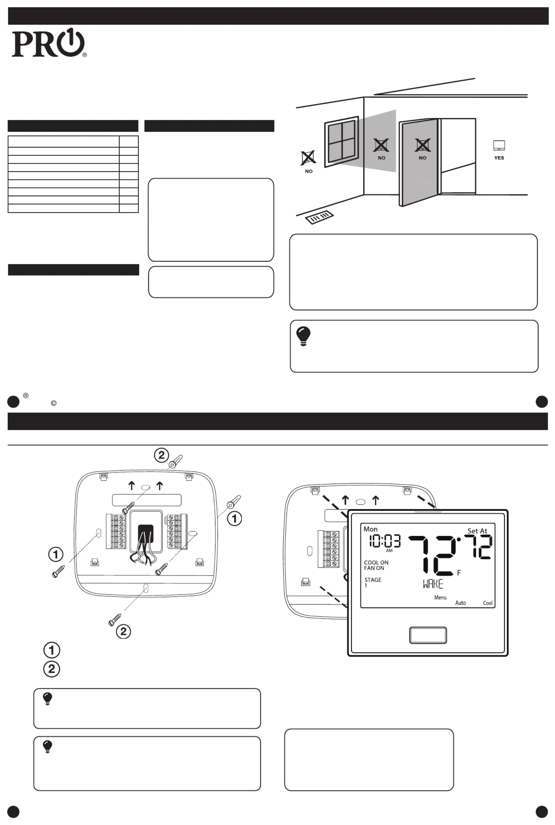
Mount Thermostat
Align the 4 tabs on the subbase with
corresponding slots on the back of the
thermostat, then push gently until the
thermostat snaps in place.
Installation Tips
2
2
2
2
Note:To ensure a solid t between the
thermostat and the subbase:
1. Mount subbase to a at wall
2. Use screws provided
3. Drywall anchors should be ush with the wall
4.Wires should be pushed into the wall
Installation Tips
The thermostat should be installed approximately 4 to 5 feet above the
oor. Select an area with average temperature and good air circulation.
• Close to hot or cold air ducts
• That are in direct sunlight
• With an outside wall behind the thermostat
• In areas that do not require conditioning
• Where there are dead spots or drafts (in corners or behind doors)
• Where there might be concealed chimneys or pipes
Wall Locations
Pick an installation location that is easy for the user to access. The temperature
of the location should be representative of the building.
Installation Tip
Do not install thermostat in these locations:
3
3
3
3
4
4
4
4
Installation Tips
22-29
30
Vertical Mount
Horizontal Mount
For horizontal mount put one screw on
the left and one screw on the right.
All of our products are mercury free. However, if the product you are
replacing contains mercury, dispose of it properly. Your local waste
management authority can give you instructions on recycling and
proper disposal.
Mercury Notice
Failure to disconnect the power before beginning to install this product
can cause electrical shock or equipment damage.
Installation Tip: Electrical Hazard
For vertical mount put one screw on
the top and one screw on the bottom.
Subbase Installation
11-12
9-10
P.O. Box 3377
Springeld, MO 65808-3377
31
Rev. 2214
T855
Produktspecifikationer
| Varumärke: | Pro1 |
| Kategori: | Termostat |
| Modell: | T855 |
Behöver du hjälp?
Om du behöver hjälp med Pro1 T855 ställ en fråga nedan och andra användare kommer att svara dig
Termostat Pro1 Manualer

2 April 2026
1 April 2026
31 Mars 2026
30 Mars 2026
24 Augusti 2025
24 Augusti 2025
24 Augusti 2025
24 Augusti 2025
24 Augusti 2025
24 Augusti 2025
Termostat Manualer
Nyaste Termostat Manualer
19 Mars 2026
16 Mars 2026
14 Mars 2026
25 Februari 2026
13 Oktober 2025
12 Oktober 2025
12 Oktober 2025
5 Oktober 2025
2 Oktober 2025
2 Oktober 2025