Qubino Flush Heat & Cool Bruksanvisning
Läs gratis den bruksanvisning för Qubino Flush Heat & Cool (2 sidor) i kategorin Termostat. Guiden har ansetts hjälpsam av 27 personer och har ett genomsnittsbetyg på 4.5 stjärnor baserat på 14 recensioner. Har du en fråga om Qubino Flush Heat & Cool eller vill du ställa frågor till andra användare av produkten? Ställ en fråga
Sida 1/2

Qubino
The and INNOVATIVE SMALLEST
Flush Heat Cool Thermostat &
ORDERING CODE
Z-WAVE FREQUENCY
ZMNHK D1
868,4 MHz
ZMNHK D2
921,4 MHz
ZMNHK D3
908,4 MHz
ZMNHK D4
869,0 MHz
ZMNHK D5
916,0 MHz
ZMNHKD8
865,2 MHz
This Z-Wave module is used to regulate temperature in
heating and cooling mode. Module can be controlled either
through Z-Wave network or through the wall switch.
The module is designed to be mounted inside a ush “fl
mounting and is hidden behind a traditional wall switch. box”
Module measures power consumption of connected device.
It is designed to act as repeater in order to improve range
and stability of Z-wave network.
Supported switches
Module supports switches (push button) and mono-stable
bi-stable switches. The module is factory set to operate
with bi-stable switches.
Installation
To prevent electrical shock and/or equipment damage,
disconnect electrical power at the main fuse or circuit
breaker before installation or any servicing.
Make sure, that no voltage is present in the installation.
Prevent the disconnecting device from being switched on
accidentally.
Connect the module according to electrical diagram.
Locate the antenna far from metal elements (as far as
possible).
Do not shorten the antenna.
Danger of electrocution!
Module installation requires a great degree of skill and
may be performed only by a qualified and licensed
electrician.
Even when the module is turned off, voltage may be
present on its terminals.
Note!
Do not connect the module to loads exceeding
recommended values. Connect the module only in
accordance to the below diagrams. Improper connections
may be dangerous.
Electrical installation must be protected by directly
associated over current protection fuse 4A, gG or Time
lag T, rated breaking capacity 1500A (ESKA 522.723)
must be used according to wiring diagram to achieve
appropriate overload protection of the module. The fuse
must be installed in fuse holder: Adels contact 503 Si / 1DS
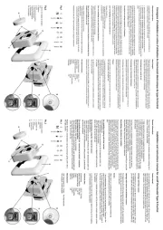
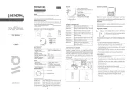
Package contents:
Flush Thermostat + Temperature sensor Heat & Cool
Electrical diagram 230VAC
Notes for the diagram:
N
Neutral lead
L
Live lead
Q1
Output for Heating valve
Q2
Output for Cooling valve
I2
Input for switch /push button or sensor*
I1
Input for switch /push button or sensor*
TS
Terminal for digital temperature sensor (only for
Flush Heat & Cool thermostat module compatible
digital temperature sensor).
*For details please check parameters 11 and 12
Electrical diagram 24VDC
Notes for the diagram:
N
+ VDC
L
- VDC
Q1
Output for Heating valve
Q2
Output for Cooling valve
I2
Input for switch /push button or sensor*
I1
Input for switch /push button or sensor*
TS
Terminal for digital temperature sensor (only for
Flush Heat & Cool thermostat module compatible
digital temperature sensor).
*For details please check parameters 11 and 12
WARNING: Service button S when must NOT be used
module is connected to 110-230V power supply.
Durability of the device depends on applied load. For
resistive load (light bulbs, etc.) and 4A current consumption
of each individual electrical device, the durability exceeds
70.000 switches of each individual electrical device.
Module Inclusion (Adding to Z-wave network)
Connect module to power supply (with
temperature sensor connected),
auto-inclusion (works for about 5 seconds after
connected to power supply) or
press push button I1 three times within 3s (3 times
change switch state within 3 seconds) or
press service button (only applicable for 24 V SELV S
supply voltage) for more than 2 second.
NOTE1: For auto-inclusion procedure, first set main
controller into inclusion mode and then connect module to
power supply.
NOTE2: When connecting temperature sensor to module
that has already been included, you have to exclude
module first. Switch off power supply, connect the sensor
and re-include the module .
Module Exclusion/Reset (Removing from Z-
Wave network)
Connect module to power supply
bring module within maximum 1 meter (3 feet) of the
main controller,
enable add/remove mode on main controller,
press push button five times within 3s (5 times change I1
switch state within 3 seconds) in the first 60 seconds
after the module is connected to the power supply or
press service button (only applicable for 24 V SELV S
supply voltage) for more than 6 second.
By this function all parameters of the module are set to
default values and own ID is deleted.
If push button I1 is pressed three times within 3s (or service
button S is pressed more than 2 and less than 6 seconds)
module is excluded, but configuration parameters are not
set to default values.
NOTE: If the module is included with parameters 100 or
101 with value different to default and module reset is done,
wait at least 30s before next inclusion.
Association
Association enables Flush thermostat module Heat & Cool
to transfer commands inside Z-Wave network directly
(without main controller) to other Z-Wave modules.
Associated Groups:
Group 1: Lifeline group (reserved for communication with
the main controller), 1 node allowed.
Group 2: basic on/off (triggered at change of the output Q1
or Q2 state and reflecting its state) up to 16 nodes.
Group 3: SENSOR_MULTILEVEL_GET (triggered once per
minute if parameter 121 is not 0) up to 16 nodes.
Group 4: basic on/off (triggered by Too high temperature
limit, it send , triggered by To Low temperature, it send 0x00
0xFF) up to 16 nodes.
Group 5: THERMOSTAT_SETPOINT_G (triggered once ET
per minute if parameter 121 is not 0) up to 16 nodes.
Group 6: basic on/off (trigged by change of I1 if window
sensor functionality is selected by parameter no. 11) up to
16 nodes.
Group 7: basic on/off (trigged by change of I2 if condense
sensor functionality is selected by parameter no. 12) up to
16 nodes.
Group 9: sensor multilevel report (trigged by change of
temperature) up to 16 nodes.
Configuration parameters
Parameter no. 1 Input I1 switch type –
Available config. parameters (data type is 1 Byte DEC):
default value 1
- mono-stable switch type (push button) 0
- -stable switch type 1 bi
Parameter no. 2 Input I2 switch type –
See parameter 1 (valid for I2 instead of I1)
Parameter no. 4 Input 1 contact type –
Available config. parameters (data type is 1 Byte DEC):
default value 0
- NO (normally open) input type 0
- NC (normally close) input type 1
NOTE: This parameter has influence only when parameter
no. 11 is set to the value “2”. After setting this parameter,
switch the window sensor once, so that the module could
determine the input state.
Parameter no. 5 Input 2 contact type –
See parameter 4 (valid for I2 instead of I1)
NOTE: This parameter has influence only when parameter
no. 12 is set to the value “2000”. After setting this
parameter, switch the condense sensor once, so that the
module could determine the input state.
Parameter no. 10 - Activate / deactivate functions ALL
ON/ALL OFF
Available config. parameters (data type is 2 Byte DEC):
default value 255
- ALL ON active, ALL OFF active. 255
- ALL ON is not active ALL OFF is not active 0
- ALL ON is not active ALL OFF active 1
- ALL ON active ALL OFF is not active 2
Flush thermostat module responds to Heat & Cool
commands ALL ON / ALL OFF that may be sent by the
main controller or by other controller belonging to the
system.
Parameter no. 11- I1 Functionality selection
Available config. parameters (data type is 2 Byte DEC):
default value 1
input I1 does influence on the Heat & Cool 32767 – n’t
process
- input I1 changes the mode of the thermostat between 1
Off and Auto. In this case function on window sensor is
disabled
- input I1 influences on cooling and heating valves 2
according to status of window sensor. In this case
function of Off and Auto selection by I1 is disabled.
NOTE: If "Window Sensor" selected (value set to "2"),
parameter 100 (enable/disable endpoint) must be set to
non-zero value and module re-included!
Parameter no. 12 I2 Functionality selection –
Available config. parameters (data type is 2 Byte DEC):
default value 32767
- input I2 does not influence on the Heat & Cool 32767
process
From 0 to 990 - Temperature set point from 0.0 °C to
99.0 °C. When I2 is pressed, it automatically set Heat
and Cool temperature setpoint according to value s
defined here. In this case function of condense sensor is
disabled
From 1001 to 1150 - Temperature set point from -0.1 °C
to - . When I2 is pressed, it automatically set 15.0 °C
temperature setpoint according to value defined here. In
this case function of condense sensor is disabled
- Input I2 influences on the cooling valve according 2000
to status of condense sensor, In this case function of
setpoint selection with I2 is disabled
NOTE: If "Condense Sensor" selected (value set to "2000"),
parameter 101 (enable/disable endpoint) must be set to
non-zero value and module re-included!
Parameter no. 40 Power reporting in Watts on power –
change
Set value means percentage, set value from 0 - 100=0% -
100%. Available configuration parameters (data type is 1
Byte DEC):
default value 0
- reporting disabled 0
1-100 = 1%-100% Reporting enabled. Power report is
send (push) only when actual power in Watts in real time
changes for more than set percentage comparing to
previous actual power in Watts, step is 1%.
NOTE If power changed is less than 1W, the report is not :
send (pushed), independent of percentage set.
Parameter no. 42 Power reporting in Watts by time –
interval
Set value means time interval (0 ) in seconds, –32767
when power report is send. Available config. parameters
(data type is 2 Byte DEC):
default value 0 (power report is disabled)
- reporting disabled 0
- = 1 second - seconds. Reporting 1 32767 32767
enabled. Power report is send with time interval set by
entered value.
Parameter no. 43 Hysteresis Heating – On
This parameter defines temperature difference between
measured temperature and set-point temperature to turn
heating on. Available configuration parameters (data type is
2 Byte DEC):
default value 1010 (-1.0 °C)
- 25,5 0 255 = 0,0°C to °C
- 1 = - - 25,5 1001 255 0,1°C to °C
Parameter no. 44 - Hysteresis Heating Off
This parameter defines temperature difference between
measured temperature and set-point temperature to turn
heating off. Available configuration parameters (data type is
2 Byte DEC):
default value 2 (+0.2 °C)
- 25,5 0 255 = 0,0°C to °C
- 1 = - - 25,5 1001 255 0,1°C to °C
Parameter no. 45 Hysteresis Cooling – On
This parameter defines temperature difference between
measured temperature and set-point temperature to turn
cooling on. Available configuration parameters (data type is
2 Byte DEC):
default value 5 (+0.5 °C)
- 25,5 0 255 = 0,0°C to °C
- 1 = - - 25,5 1001 255 0,1°C to °C
Parameter no. 46 Hysteresis Cooling Off –
This parameter defines temperature difference between
measured temperature and set-point temperature to turn
cooling off. Available configuration parameters (data type is
2 Byte DEC):
default value 1002 (- 0.2 °C)
- 25,5 0 255 = 0,0°C to °C
- 1 = - - 25,5 1001 255 0,1°C to °C
Parameter no. 47 –Antifreeze
Set value means at which temperature the device will be
turned on even if the thermostat was manually set to off.
Available config. parameters (data type is 2 Byte DEC):
default value 50 (5,0 °C)
- 0 127 = 0,0°C to 12,7 °C
- 1127 = - - 1001 0,1°C to 12,7 °C
- Antifreeze functionality disabled 255
NOTE: Antifreeze is activated only in heating mode. It uses
a hysteresis determined parameters no. 43 and 44. in
Parameter no. 60 Too low temperature limit –
Available config. parameters (data type is 2 Byte DEC):
default value (too low temperature limit is 5 50 .0°C)
- - 1 1000 = 0.1°C 100.0°C, step is 0.1°C.
1150 = - - 1001 – 0.1°C to 15.0°C
NOTE: Too l temperature limit is used with Association ow
Group 4.
Parameter no. 61 Too high temperature limit –
Available config. parameters (data type is 2 Byte DEC):
d efault value 700 (too high temperature limit is 70.0°C)
- - 1 1000 = 0.1°C 100.0°C, step is 0.1°C. Too high
temperature limit is used with Association Group 4.
Parameter no. 64 Output Switch selection –Q1
Set value means the type of the device that is connected to
the output. The device type can be normally open (NO) Q1
or normally close (NC).
Available config. parameters (data type is 1 Byte DEC):
default value 0
- When system is turned off the output is 0 V. 0
- When system is turned off the output is 230 V. 1
Parameter no. 65 Output Switch selection –Q2
Set value means the type of the device that is connected to
the output. The device type can be normally open (NO) Q2
or normally close (NC).
Available config. parameters (data type is 1 Byte DEC):
default value 0
- When system is turned off the output is 0 V. 0
- When system is turned off the output is 230 V. 1
Parameter no. 70 Input 1 status on delay –
Available config. parameters (data type is 2 Byte DEC):
default value 0
- 32000 seconds 1
If the value of parameter is different to 0, means that the
Influence of this input to heating or cooling will react after
inserted time. This parameter has influence only when the
S
Service button (used to add
or remove module from the
Z-Wave network in case of
24 V SELV power supply).
Produktspecifikationer
| Varumärke: | Qubino |
| Kategori: | Termostat |
| Modell: | Flush Heat & Cool |
Behöver du hjälp?
Om du behöver hjälp med Qubino Flush Heat & Cool ställ en fråga nedan och andra användare kommer att svara dig
Termostat Qubino Manualer

16 September 2024

16 September 2024
Termostat Manualer
- Airwell
- Devolo
- Fenix
- PECO
- Robertshaw
- Helios (Amfra)
- Otio
- Mitsubishi
- Elco
- ACV
- Pro1
- Grohe
- Zehnder
- Etherma
- Velleman
Nyaste Termostat Manualer
13 Oktober 2025

12 Oktober 2025
12 Oktober 2025
5 Oktober 2025
2 Oktober 2025
2 Oktober 2025
29 September 2025

28 September 2025
28 September 2025
28 September 2025