Sanwa DCM60R Bruksanvisning
Sanwa Mätutrustning DCM60R
Läs gratis den bruksanvisning för Sanwa DCM60R (2 sidor) i kategorin Mätutrustning. Guiden har ansetts hjälpsam av 37 personer och har ett genomsnittsbetyg på 4.3 stjärnor baserat på 7 recensioner. Har du en fråga om Sanwa DCM60R eller vill du ställa frågor till andra användare av produkten? Ställ en fråga
Sida 1/2
SANWA ELECTRIC
INSTRUMENT CO.,LTD.
Dempa Bldg,Sotokanda2-Chome
Chiyoda-Ku,Tokyo,Japan
This product has been designed and manufactured in accordance with the safety
standards applicable to IEC 61010-2-32 Electronic Measuring Equipment and
has passed the inspection. Using this product in ways not specified in this
manual may damage its protection function. The instructions given under the
heading of “WARNING”must be followed to prevent ”and “CAUTION
accidents.
WARNING: Intended to prevent personal injury such as burn and electric
shock and other serious accidents.
CAUTION : Intended to prevent misuse that could result in personal
injury and damage to equipment including this instrument.
Safety Information - Before use, read manual -
Clamp type current sensor (CT)
Max. ø25 mm
Max. 1999 counts, units, symbols
Δ-Σ method
True RMS
2 times/sec
“OL”is displayed
is displayed
When the battery is under approx. 2.2 V,
symbol will appear on the LCD display.
IEC61010-1, IEC61010-2-030 CAT.III 300 V/II 600 V
,
IEC61010-2-032, IEC61010-2-033, IEC61010-31
Altitude up to 2000 meters, indoor use, pollution degree 2
3700 Vrms
23 °C ± 5 °C,<80 % RH, No condensation
0 °C ~ 40 °C,<80 % RH, No condensation
–10 °C ~ 60 °C,<70 % RH, No condensation
R03 (UM-4) or AAA 1.5 V battery x 2
Approx. 5.0 mW/approx. 250 hr
Approx. 187 (0(H) x 5W) x 29 (D) mm
Approx. 210 g (including battery)
Instruction Manual, Carrying Case (C-DCM60L),
Test Lead (TL-21a)
General Specification
Measurement method:
Clamp opening size:
Digital display:
Operation method:
AC detection method:
Sample rate:
Over-range display:
Data hold:
Low power indication:
Safety standards:
Environmental conditions:
Withstand voltage:
Accuracy assurance
temperature/humidity:
Operating
temperature/humidity:
Storage
temperature/humidity:
Power Source:
Power
consumption/battery life:
Dimensions/Mass:
Accessory:
Specification
The accuracy specification is defined as ±( …%reading+…count )
At 23± 5 ˚C, 80 %RH
Buzzer sounds at 100 Ω or less.
rdg = reading, dgt = digit
ACV/ACA range: 1 % ~ 100 % of the measurement range
Crest Factor (CF):CF<1.6 at full scale & CF<3.2 at half scale
Measurement Categories (Overvoltage Categories)
This instrument is a true rms AC clamp meter designed in compliance with
IEC61010-1 CAT.III 300 V/CAT.II 600 V. It is suitable for measuring the
current of electrical lines, appliances and power supply facilities operating on
low voltages of no more than 600 V.
CAT.: Primary cable runs of power-consuming equipment from a wall socketII
CAT.III: Primary cable runs of equipment directly connected to a distribution
board and cable runs from a distribution board to wall sockets.
Crest Factor
The CF (crest factor) indicates the peak value of a signal by dividing it by its
root-mean-square value. With most common waveforms such as sinusoidal
wave and chopping wave, the crest factor is low. With low duty cycle pulse
waveforms, the crest factor is high. For the voltages and crest factors for
typical waveforms, see the table below.
Range
199.9 Ω
Resolution
0.1 Ω
Accuracy
±1.9 %rdg.+3dgt.
MAX Test
Voltage
1.0 VDC
Overload
Protection
500 Vrms
Ohm (Ω) Continuity( )
Electrical Specification
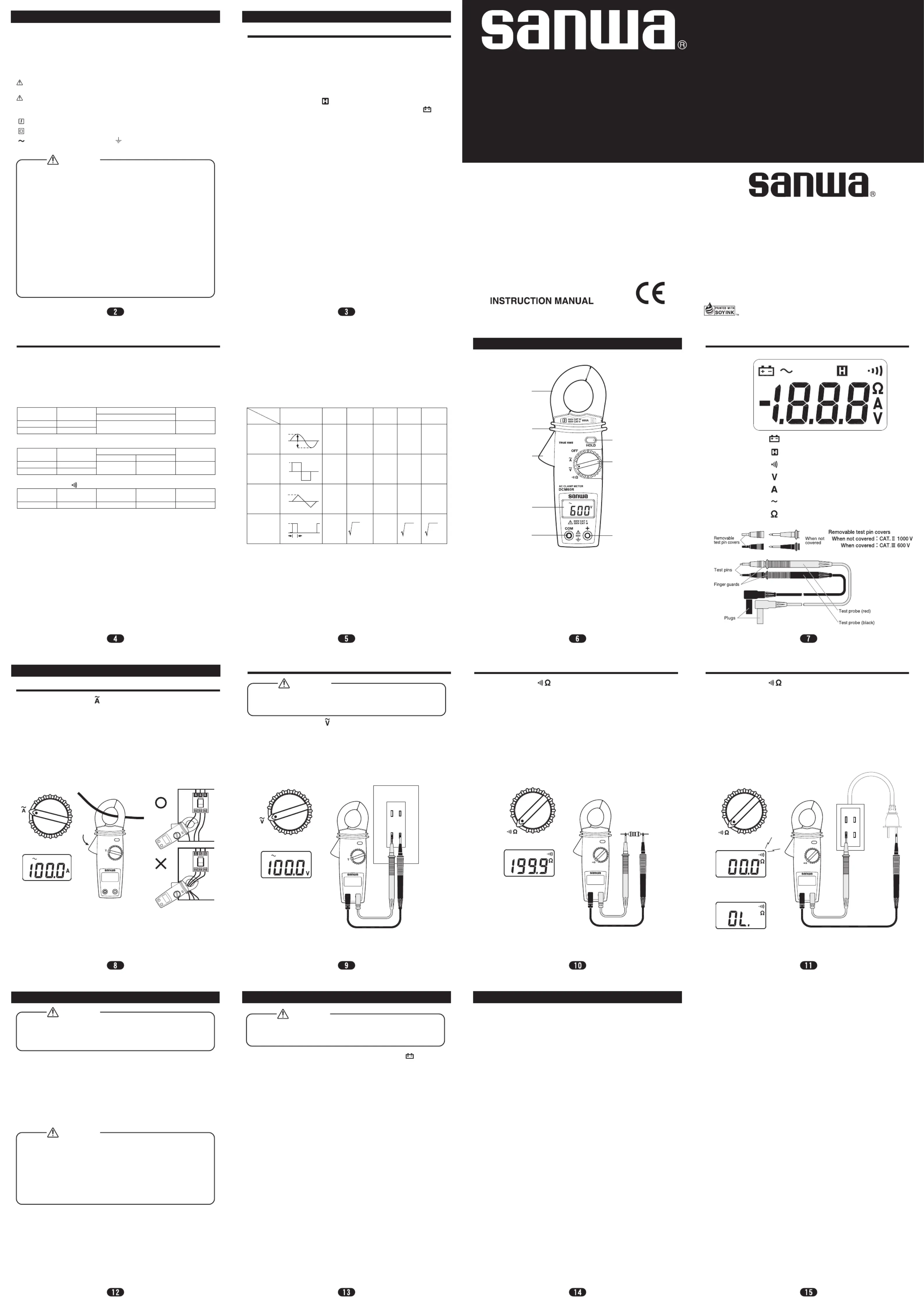
Instrument Familiarization
Low battery indication
Hold Data indication
Continuity function indication
Voltage measurement indication
Current measurement indication
Alternative source indication
Resistance
Symbol Definition
Switch the function selector to range.
Open the clamp by pressing the jaw-opening handle and insert the cable to be
measured into the jaw.
Close the clamp and get the reading from the LCD display.
Note:
Before this measurement, disconnect the test lead with the meter for safety.
In some occasion that the reading is hard to read, push the HOLD button and
read the result later.
Measuring Instruction
AC Current Measurement
Switch the function selector to range.
Connect red test lead to “+” terminal and black one to the “ COM ” terminal.
Measure the voltage by touch the test lead tips to the test circuit where the
value of voltage is needed.
Read the result from the LCD display.
ACV Measurement
Switch the function to range.
Connect red test lead to “+” terminal and black one to the “ COM ” terminal.
Connect tip of the test leads to the points where the value of the resistance is
needed.
Read the result from the LCD display.
Note:
When take resistance value from a circuit system, make sure the power is cut
off and all capacitors need to be discharged.
1. Maintenance and Inspection
Appearance: Is the meter not damaged due to falling or other cause?
If any of the above problems exists, stop using the meter and request for
repair.
2. Inspection
Inspect the meter at least once a year.
3. Storage
4. Battery when the meter is shipped:
A battery for monitoring has been installed prior to shipment from the
factory. It may be discharged before the expiration of the described battery
life.
*The battery for monitoring is a battery used to check the functions and
performance of the product.
Resistance Measurement
Switch the function to range.
Connect red test lead to “+” terminal and black one to the “ COM ” terminal.
Connect tip of the test leads to the points where the conduction condition
needed.
If the resistance is under 100 Ω, the beeper will sound continuously.
Note:
When take resistance value from a circuit system, make sure the power is cut
off and all capacitors need to be discharged.
Continuity Test
Maintenance
Maximum Input Voltage is 600 VAC. Do not attempt to take any voltage
measurement that may exceed to avoid Electrical shock hazard and/or
damage to this instrument.
WARNING
1. This is a clamp meter for low-voltage circuits. Never use it on the power
line that exceeds 600 VAC to ground. The measurement classification
category of this instrument is CAT. III 300 V/ CAT. II 600 V.
2. Use the meter only as described in this manual.
3. Do not apply more than the rated maximum input .
4. Pay special attention to voltages above 33 VAC (46.7 Vpeak) and
70 VDC that are hazardous to the human body.
5. Do not use the meter if it is damaged or broken.
6. Do not use the meter with the rear case removed.
7. During measurement, keep your fingers behind the barrier (finger
guard).
8. When measuring un-insulated conductors, be careful not to touch
them. Otherwise you will suffer electric shock.
9. Do not use the meter near flammable gases or solvents.
10. Do not use the meter with wet hands or in a damp environment.
11. Do not disassemble or modify the meter nor use components not
specified by the manufacturer.
12. Inspect the meter at least once a year.
13. The meter is for indoor use.
WARNING
Accuracy
50 Hz400 Hz〜
±1.5 %rdg.+5dgt.
Overload
Protection
660 Vrms
Range
199.9 V
600 V
Resolution
0.1 V
1 V
ACV (Autorange)
Resolution
0.1 A
1 A
Accuracy
Overload
Protection
600 Arms
Range
199.9 A
600 A
ACA (Autorange)
50 Hz〜60 Hz
±2 %rdg.+5dgt.
60 Hz〜400 Hz
±2.9 %rdg.+5dgt.
①Current Sensing Clamp
②Barrier
③Clamp opening handle
④LCD display
⑤COM input terminal
⑥Positive input terminal
⑦Function selector
⑧Data hold button
1. The following instructions are very important for safety. Read this
manual thoroughly to ensure correct maintenance.
2. Calibrate and inspect the meter at least once a year to ensure safety
and maintain its accuracy.
WARNING
1. The panel and case are not resistant to volatile solvent and must not
be cleaned with thinner or alcohol.
2. The panel and case are not resistant to heat. Do not place the meter
near heat-generating devices.
3. Do not store the meter in a place where it may be subjected to
vibration or from where it may fall.
4. Do not store the meter in places under direct sunlight, or hot, cold or
humid places or places where condensation is anticipated.
5. If the meter will not be used for a long time, remove the battery.
CAUTION
①
②
③
④
⑤
⑧
⑦
⑥
Battery Changing
1. When the battery voltage drop below approx. 2.2 V the symbol will
appear on the LCD display and the battery need to changed.
2. Before changing the battery, switch the function selector to “OFF ”and
disconnect test leads.Open the rear case by a screwdriver. Replace the
old batteries with two R03 or AAA size batteries.
3. Close the rear case and fasten the screw.
To prevent electrical hazard or shock, turn off clamp meter and disconnect
test leads before removing rear case.
Never uses the meter before the rear case is closed.
WARNING
1. Warranty and Provision
Sanwa offers comprehensive warranty services to its end-users and to its
product resellers. Under Sanwa's general warranty policy, each instrument
is warranted to be free from defects in workmanship or material under
normal use for the period of one (1) year from the date of purchase.
This warranty policy is valid within the country of purchase only, and
applied only to the product purchased from Sanwa authorized agent or
distributor.
Sanwa reserves the right to inspect all warranty claims to determine the
extent to which the warranty policy shall apply. This warranty shall not
apply to disposables batteries, or any product or parts, which have been
subject to one of the following causes:
1) A failure due to improper handling or use that deviates from the
instruction manual.
2) A failure due to inadequate repair or modification by people other than
Sanwa service personnel.
3) A failure due to causes not attributable to this product such as fire, flood
and other natural disaster.
4) Non-operation due to a discharged battery.
5) A failure or damage due to transportation, relocation or dropping after
the purchase.
2. Repair
Customers are asked to provide the following information when requesting
services:
1) Customer name, address, and contact information
2) Description of problem
3) Description of product configuration
4) Model Number
5) Product Serial Number
6) Proof of Date-of-Purchase
7) Where you purchased the product
Please contact Sanwa authorized agent / distributor / service provider,
listed in our website, in your country with above information. An
instrument sent to Sanwa / agent / distributor without above information
will be returned to the customer.
Note :
1) Prior to requesting repair, please check the following:
Capacity of the built-in battery, polarity of installation and discontinuity
of the test leads.
2) Repair during the warranty period:
The failed meter will be repaired in accordance with the conditions
stipulated in 1 Warranty and Provision.
3) Repair after the warranty period has expired:
In some cases, repair and transportation cost may become higher than
the price of the product. Please contact Sanwa authorized agent /
service provider in advance.
The minimum retention period of service functional parts is 6 years
after the discontinuation of manufacture. This retention period is the
repair warranty period. Please note, however, if such functional parts
become unavailable for reasons of discontinuation of manufacture, etc.,
the retention period may become shorter accordingly.
4) Precautions when sending the product to be repaired:
To ensure the safety of the product during transportation, place the
product in a box that is larger than the product 5 times or more in
volume and fill cushion materials fully and then clearly mark “Repair
Product Enclosed” on the box surface. The cost of sending and
returning the product shall be borne by the customer.
3. SANWA web site
http://www.sanwa-meter.co.jp
E-mail: exp_sales@sanwa-meter.co.jp
After - Sale Service
DCM60R
DIGITAL CLAMP METER
:Ground
:Double or reinforced insulation
:
Application around and removal from hazardous live conductors is permitted
:Alternating current (AC)
Input Waveform
0 to PEAK
Vrms
Average
Value
Crest
Factor
Form
Factor
Root Mean
Square Value
Vavg
Vp/Vrms
Vrms/Vavg
Sinusoidal
wave
Square
wave
Chopping
wave
Pulse
=1.414
=1.111
Vp
Vp
Vp
1
0
0
pp
Vp
Vp
0
Vp
−
Vp
2
2
√
√
=0.707 Vp
−
2Vp
π
=0.637 Vp
Vp
−
2
√
2
π
2π
π
π
VpVp1
π
2π
2π
−
Vp
3
√
=0.577 Vp
−
Vp
2
=0.5 Vp
−
2
3
√
=1.155
3
√
=1.732
2π
τ
0
Vp
−
τ
2π
・
Vp
−
τ
2π
・
Vp
−
2π
τ
−
2π
τ
Vp
Voltages of Various Waveforms
TL-21a
Continuity
(Buzzer sounds.)
Disconnection
Beep
Open
Produktspecifikationer
| Varumärke: | Sanwa |
| Kategori: | Mätutrustning |
| Modell: | DCM60R |
Behöver du hjälp?
Om du behöver hjälp med Sanwa DCM60R ställ en fråga nedan och andra användare kommer att svara dig
Mätutrustning Sanwa Manualer

18 September 2024
18 September 2024
18 September 2024
17 September 2024
17 September 2024
17 September 2024
17 September 2024
17 September 2024
17 September 2024
17 September 2024
Mätutrustning Manualer
Nyaste Mätutrustning Manualer
3 April 2025
3 April 2025
3 April 2025
3 April 2025
3 April 2025
3 April 2025
3 April 2025
3 April 2025
3 April 2025
3 April 2025