Shelly Wave Shutter Bruksanvisning
Shelly Smarth hem Wave Shutter
Läs gratis den bruksanvisning för Shelly Wave Shutter (4 sidor) i kategorin Smarth hem. Guiden har ansetts hjälpsam av 38 personer och har ett genomsnittsbetyg på 4.9 stjärnor baserat på 6 recensioner. Har du en fråga om Shelly Wave Shutter eller vill du ställa frågor till andra användare av produkten? Ställ en fråga
Sida 1/4
NLO1O2
S
W
1S
W
2
Fig.1/
Abb.1/
Imagen 1/
Image 1
B3223
Wave Shutter
Fig.2/
Abb.2/
Imagen 2/
Image 2
Fig.3/
Abb.3/
Imagen 3/
Image 3
V 0.0.21/2
Fig.4/
Abb.4/
Imagen 4/
Image 4
S
Fig.5/
Abb.5/
Imagen 5/
Image 5
NLO1O2
S
W
1S
W
2
NLO1O2
S
W
1S
W
2
NLO1O2
S
W
1S
W
2
NLO1O2
S
W
1S
W
2
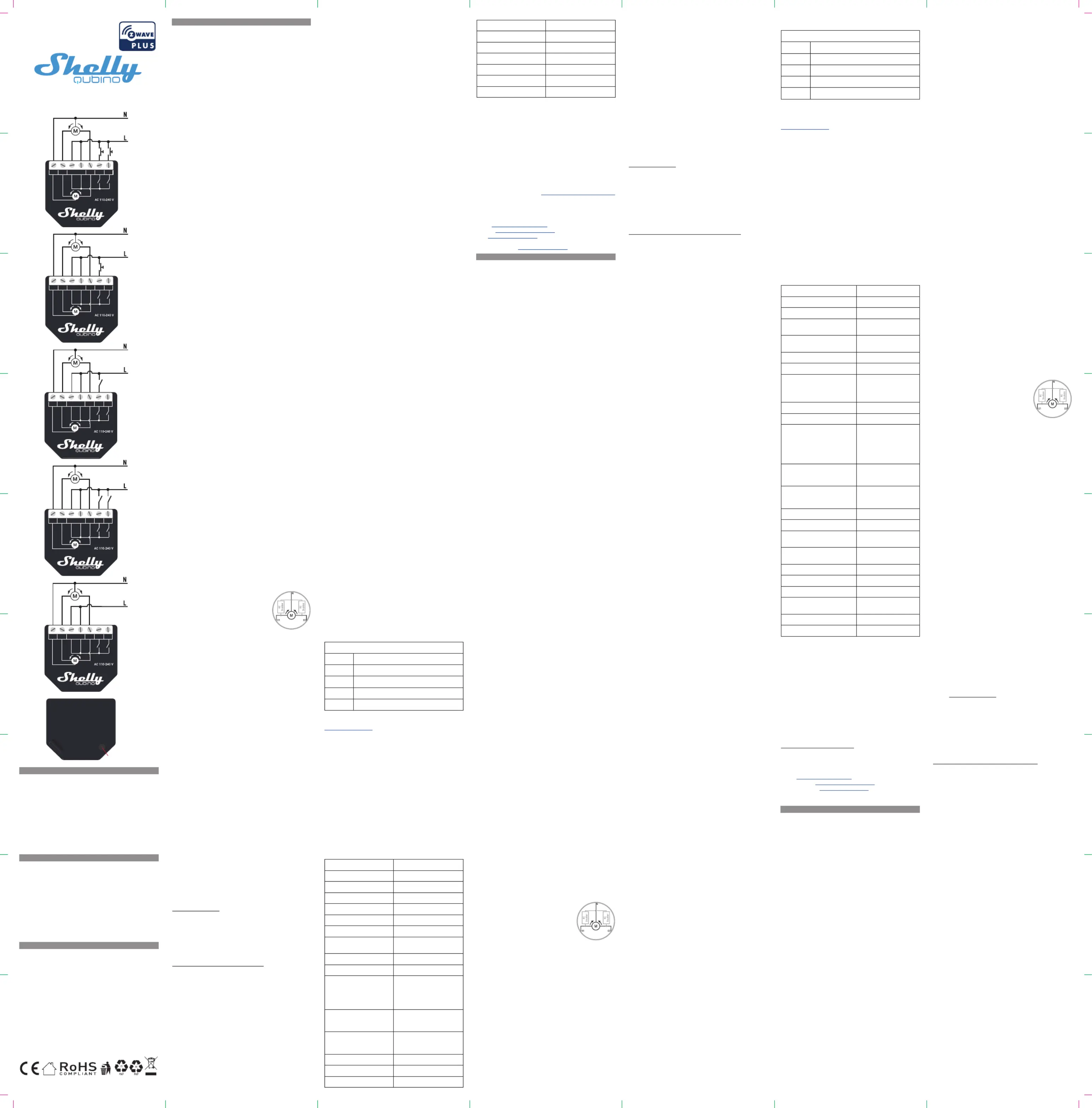
EN
LEGEND
Device terminals:
•N: Neutral terminal
•L: Live terminals (110–240 V AC)
•O1: Output terminal for motor UP (open)
•O2: Output terminal for motor DOWN (close)
•SW1: Input terminal for switch/push-button UP (open)
•SW2: Input terminal for switch/push-button DOWN (close)
Wires:
•N: Neutral wire
•L: Live wire (110-240 V AC)
Button:
•S: S button (Fig. 6)
DE
LEGENDE
Geräteanschlüsse:
•N: Klemme für Neutralleiter
•L: Klemmen für Phase (110-240 V AC)
•O1: Ausgangsklemme für Motor AUF (offen)
•O2: Ausgangsklemme für Motor AB (schließen)
•SW1: Eingangsklemme für Schalter/Taster AUF (offen)
•SW2: Eingangsklemme für Schalter/Taster AB (schließen)
Kabel:
•N: Neutralleiter
•L: Phasenleiter (110 - 240 V AC)
Taste:
•S: Die S-Taste (Abb. 6)
IT
LEGENDA
Terminali del Dispositivo:
•N: Terminale neutro
•L: Terminali sotto tensione (110-240 V CA).
•O1: Terminale di uscita per il motore SU (apertura)
•O2: Terminale di uscita per il motore GIÙ (chiusura)
•SW1: Terminale di ingresso per il pulsante/interuttore SU (ap-
ertura)
•SW2: Terminale di ingresso per il pulsante/interuttore GIÙ (chi-
usura)
Fili:
•N: Filo neutro
•L: Filo sotto tensione (110 - 240 V CA)
Pulsante:
•S: Pulsante S (Fig. 6)
Fig.6/
Abb.6/
Imagen 6/
Image 6
EN
USER AND SAFETY GUIDE
Z-Wave™ shutter control with power
measurement
READ BEFORE USE
This document contains important technical and safety informa-
tion about the Device, its safe use and installation.
⚠CAUTION!Before beginning the installation, please read carefully
and entirely this guide and any other documents accompanying the
Device. Failure to follow the installation procedures could lead to
malfunction, danger to your health and life, violation of law or refusal
of legal and/or commercial guarantee (if any). Shelly Europe Ltd. is
not responsible for any loss or damage in case of incorrect installa-
tion or improper operation of this Device due to failure of following
the user and safety instructions in this guide.
TERMINOLOGY
Gateway–A Z-Wave™ gateway, also referred to as a Z-Wave™
controller, Z-Wave™ main controller, Z-Wave™ primary controller, or
Z-Wave™hub, etc., is a device that serves as a central hub for a
Z-Wave™smart home network. The term “” is used in this gateway
document.
S button- The Z-Wave™ Service button, which is located on Z-Wave™
devices and is used for various functions such as inclusion (add-
ing), exclusion (removing), and resetting the device to its factory
default settings. The term "" is used in this document.S button
Device Device– In this document, the term “” is used to refer to the
Shelly Qubino device that is a subject of this guide.
ABOUT SHELLY QUBINO
Shelly Qubino is a line of innovative microprocessor-managed
devices, which allow remote control of electric circuits with a
smartphone, tablet, PC, or home automation system. They work on
Z-Wave™ wireless communication protocol, using a gateway. When
the gateway is connected to the internet, you can control Shelly
Qubino devices remotely from anywhere. Shelly Qubino devices can
be operated in any Z-Wave™ network with other Z-Wave™ certied
devices from other manufacturers. All mains operated nodes within
the network will act as repeaters regardless of vendor to increase
reliability of the network. Devices are designed to work with older
generations of Z-Wave™ devices and gateways.
ABOUT THE DEVICE
The Device enables remote control of motorized blinds, roller shut-
ters, venetian blinds, awnings, etc. It measures power consumption
of the connected device.
It is recommended to use only motors for blinds with electronic or
mechanical limit switches. Motor limit switches must be set cor-
rectly before connecting the Device to the motor.
ELECTRICAL DIAGRAM (110–240 V AC)
Connecting to the power grid with power supply 110-240 V AC (Fig.
1-5).
INSTALLATION INSTRUCTIONS
The Device can control a bi-directional AC motor.
It can be retrotted into standard electrical wall boxes, behind the
switches or other places with limited space.
⚠CAUTION! Danger of electrocution. Mounting/installation of the
Device to the power grid has to be performed with caution, by a
qualied electrician.
⚠CAUTION! Danger of electrocution. Every change in the connec-
tions has to be done after ensuring there is no voltage present at
the Device terminals.
⚠CAUTION! Use the Device only with a power grid and appliances
that comply with all applicable regulations. A short circuit in the
power grid or any appliance connected to the Device may damage
it.
⚠CAUTION!Do not connect the Device to appliances exceeding
the given max. load!
⚠CAUTION! Do not shorten the antenna.
⚠RECOMMENDATION: Place the antenna as far away as possible
from metal elements as they can cause signal interference.
⚠CAUTION!Connect the Device only in the way shown in these
instructions. Any other method could cause damage and/or injury.
⚠CAUTION! Do not install the Device where it can get wet.
⚠CAUTION! Do not use the Device if it has been damaged!
⚠CAUTION!Do not attempt to service or repair the Device your-
self!
⚠RECOMMENDATION:Connect the Device using solid sin-
gle-core wires with increased insulation heat resistance not less
than PVC T105°C (221°F).
⚠CAUTION!Before starting the mounting/installation of the De-
vice, check that the breakers are turned off and there is no voltage
on their terminals. This can be done with a phase tester or multi-
meter. When you are sure that there is no voltage, you can proceed
to connecting the wires.
If you want to use the Device with a push-button, refer to the Fig. 1
and Fig. 2. For a switch, refer to the Fig. 3 and Fig. 4.
⚠CAUTION! Use only one phase AC circuit. Do not use mixed AC
and DC circuits.
Connect both terminals to the wire and the terminal to the LLiveN
Neutralwire. Connect the common motor terminal/wire to the Neu-
tralwire. Connect motor direction terminals/wires to the and O1
O2SW1terminals.* Connect the rst switch/push-button to the
terminal and the wire. Connect the second switch/push-button Live
to the terminal and the wire. *The Device outputs can be SW2Live
recongured to match the required rotation direction.
⚠RECOMMENDATION:For inductive appliances
that cause voltage spikes during switching on/
off, such as electrical motors, fans, vacuum
cleaners and similar ones, RC snubber (0.1 µF
/ 100 Ω / 1/2 W / 600 V AC) should be connect-
ed parallel to the appliance.
⚠CAUTION!Do not allow children to play with the push-buttons/
switches connected to the Device. Keep the devices for remote
control of Shelly Qubino (mobile phones, tablets, PCs) away from
children.
AUTOMATIC CALIBRATION
Automatic calibration is a process during which the Device learns
the position of the limit switches.
Note!For the correct position operation, the Device must perform
a calibration procedure!
Note!The motor must be equipped with electronic or mechanical
limit switches and the limit positions must be set correctly before
calibration!
Note!The calibration is successful when the Device performs a
complete cycle of movement: up, down, up, down to 50%.
Note! If the calibration is not executed, check that the limit switch-
es are correctly set and that the wiring is done according to the
instructions in the User Guide.
Automatic calibration with the push-button SW1:
Note! Calibration with the push-button SW1 is not time-limited and
can be started anytime.
1. Move blind to the top (upper) position.
2. Press SW1 4 times in 3 seconds.
3. The Device will start calibration and complete 3 cycles: down,
up, down to 50%.
4. Check the LED status to see if the calibration has been success-
ful.
Automatic calibration with the S button:
Note!Calibration with the S button is not time-limited and can be
started anytime.
1. Enter the Setting mode by pressing the S button for less than
0,5s (short press).
2. Keep pressing the S button until the calibration is selected, indi-
cated by the yellow LED colour.
3. Start calibration by pressing the S button for more than 2 sec-
onds.
4. The Device will start calibration and complete 3 cycles: down,
up, down to 50%.
5. Check the LED status to see if the calibration has been success-
ful.
VENETIAN MODE
Note! For more information about Venetian mode and this Device in
general refer to the Extended User Guide available at:
https://kb.shelly.cloud/
Z-WAVE™ ADDING / REMOVING / FACTORY RESET
Note!The blind connected to the Device will move 2s up/2s down
if the Device is successfully added to/removed from a Z-Wave™
network.
Note!In case of Security 2 (S2) adding (inclusion), a dialog will ap-
pear asking you to enter the corresponding PIN Code (5 underlined
digits) that are written on the Z-Wave™ DSK label on the side of the
Device and on the Z-Wave™ DSK label inserted in the packaging.
IMPORTANT: The PIN Code must not be lost.
Adding the Device to a Z-Wave™ network (inclusion)
SmartStart adding (inclusion):
SmartStart enabled products can be added into a Z-Wave™ network
by scanning the Z-Wave™ QR Code present on the Device with a
gateway providing SmartStart inclusion. No further action is re-
quired, and the SmartStart device will be added automatically with-
in 10 minutes of being switched on in the network vicinity.
1. With the gateway application scan the QR code on the Device
label and add the Security 2 (S2) Device Specic Key (DSK) to the
provisioning list in the gateway.
2. Connect the Device to a power supply.
3. Check if the blue LED is blinking in Mode 1. If so, the Device is not
added to a Z-Wave™ network.
4. Adding will be initiated automatically within a few seconds after
connecting the Device to a power supply, and the Device will be
added to a Z-Wave™ network automatically.
5.The blue LED will be blinking in Mode 2 during the adding pro-
cess.
6.The green LED will be blinking in Mode 1 if the Device is success-
fully added to a Z-Wave™ network.
Adding (inclusion) with a switch/push-button:
1. Connect the Device to a power supply.
2. Check if the blue LED is blinking in Mode 1. If so, the Device is not
added to a Z-Wave™ network.
3. Enable add/remove mode on the gateway.
4. Toggle the switch/push-button connected to any of the SW termi-
nals (SW, SW1, SW2, etc.) 3 times within 3 seconds (this procedure
puts the Device in Learn mode**). The Device must receive on/
off signal 3 times, which means pressing the momentary switch 3
times, or toggling the switch on and off 3 times.
5.The blue LED will be blinking in Mode 2 during the adding pro-
cess.
6.The green LED will be blinking in Mode 1 if the Device is success-
fully added to a Z-Wave™ network.
**Learn modestate allows the Device to receive network informa-
tion from the gateway.
Adding (inclusion) with the S button:
1. Connect the Device to a power supply.
2. Check if the blue LED is blinking in Mode 1. If so, the Device is not
added to a Z-Wave™ network.
3. Enable addi/remove mode on the gateway.
4. To enter the Setting mode, quickly press and hold the S button on
the Device until the LED turns solid blue.
5. Quickly release and then press and hold (> 2s) the S button on the
Device until the blue LED starts blinking in Mode 3. Releasing the S
button will start the Learn mode.
6. The blue LED will be blinking in Mode 2 during the adding pro-
cess.
7. The green LED will be blinking in Mode 1 if the Device is success-
fully added to a Z-Wave™ network.
Note!In Setting mode, the Device has a timeout of 10s before enter-
ing again into Normal mode.
Removing the Device from a Z-Wave™ network (exclu-
sion)
Note!The Device will be removed from your Z-wave™ network, but
any custom conguration parameters will not be erased.
Removing (exclusion) with a switch/push-button:
1. Connect the Device to a power supply.
2. Check if the green LED is blinking in Mode 1. If so, the Device is
added to a Z-Wave™ network.
3. Enable add/remove mode on the gateway.
4. Toggle the switch/push-button connected to any of the SW termi-
nals (SW, SW1, SW2, etc.) 3 times within 3 seconds (this procedure
puts the Device in Learn mode**). The Device must receive on/
off signal 3 times, which means pressing the momentary switch 3
times, or toggling the switch on and off 3 times.
5. The blue LED will be blinking in Mode 2 during the removing
process.
6. The blue LED will be blinking in Mode 1 if the Device is success-
fully removed from a Z-Wave™ network.
Removing (exclusion) with the S button:
1. Connect the Device to a power supply.
2. Check if the green LED is blinking in Mode 1. If so, the Device is
added to a Z-Wave™ network.
3. Enable add/remove mode on the gateway.
4. To enter the Setting mode, quickly press and hold the S button on
the Device until the LED turns Solid blue.
5. Quickly release and then press and hold (> 2s) the S button on the
Device until the blue LED starts blinking in Mode 3. Releasing the S
button will start the Learn mode.
6. The blue LED will be blinking in Mode 2 during the removing
process.
7. The blue LED will be blinking in Mode 1 if the Device is success-
fully removed from a Z-Wave™ network.
Note! In Setting mode, the Device has a timeout of 10s before enter-
ing again into Normal mode.
Factory reset
After Factory reset, all custom parameters and stored values (kWh,
associations, routings, etc.) will return to their default state. HOME
ID and NODE ID assigned to the Device will be deleted. Use this
reset procedure only when the gateway is missing or otherwise
inoperable.
Factory reset with a switch/push-button:
Note! Factory reset with the switch/push-button is only possible
within the rst minute after the Device is connected to a power
supply.
1. Connect the Device to a power supply.
2. Toggle the switch/push-button connected to any of the SW ter-
minals (SW, SW1, SW2, etc.) 5 times within 3 seconds. The Device
must receive on/off signal 5 times, which means pressing the
push-button 5 times, or toggling the switch on and off 5 times.
3. During factory reset, the LED will turn solid green for about 1s,
then the blue and red LED will start blinking in Mode 3 for approx.
2s.
4. The blue LED will be blinking in Mode 1 if the Factory reset is
successful.
Factory reset with the S button:
Note! Factory reset with the S button is possible anytime.
1. To enter the Setting mode, quickly press and hold the S button on
the Device until the LED turns Solid blue.
2. Press the S button multiple times until the LED turns Solid red.
3. Press and hold (> 2s) S button on the Device until the red LED
starts blinking in Mode 3. Releasing the S button will start the fac-
tory reset.
4. During factory reset, the LED will turn solid green for about 1s,
then the blue and red LED will start blinking in Mode 3 for approx.
2s.
5. The blue LED will be blinking in Mode 1 if the factory reset is
successful.
LED SIGNALIZATION
LED blinking modes
Mode 1 0,5s On/2s Off
Mode 2 0,5s On/0,5s Off
Mode 3 0,1s On/0,1s Off
Mode 4 (1x to 6x - 0,2s On/0,2s Off) + 2s Off
Mode 5 0,2s On blue/0,2s On red
Note! For more information about LED signalization and this Device
in general refer to the Extended User Guide available at:
https://kb.shelly.cloud/
OPERATIONAL INSTRUCTIONS
If the inputs are congured as push-buttons:
•Pressing the push-button when the blind is static, moves
the blind in the corresponding direction until the endpoint
is reached.
•Pressing the push-button for the same direction while the
blind is moving, stops the blind.
•Pressing the push-button for the opposite direction while
the blind is moving, reverses the blind movement until the
endpoint is reached.
If the inputs are congured as switches:
•Turning the switch on moves the blind in the corresponding
direction until the endpoint is reached.
•Turning the switch off stops the blind movement.
•If both switches are turned on, the Device respects the last
engaged switch. Turning off the last engaged switch stops
the blind movement, even if the other switch is still on.
•To move the blind in the opposite direction, the other
switch has to be turned off and on again.
SPECIFICATION
Power supply 110–240 V AC ±10%
Power consumption < 0.3 W
Power measurement [W]Yes
Max switching voltage AC240 V
Max switching current AC 10 A per channel
Overheating protection Yes
Overcurrent protection Yes
Distance up to 40 m indoors (131 ft.)
(depends on local condition)
Z-Wave™ repeaterYes
CPU Z-Wave™ S800
Z-Wave™ frequency bands868,4 MHz; 865,2 MHz; 869,0
MHz; 921,4 MHz; 908,4 MHz;
916 MHz; 919,8 MHz; 922,5
MHz; 919,7-921,7-923,7 MHz;
868,1 MHz; 920,9 MHz
Maximum radio frequency
power transmitted in frequen-
cy band(s)
< 25 mW
Size (H x W x D)37 mm x 42 mm x 16 mm ±
0.5 mm / 1.46 in x 1.65 in x
0.63 in ± 0.02 in
Weight29 g / 1.02 oz.
MountingWall console
Screw terminals max torque0.4 Nm / 3.5 lbin
Conductor cross section0.5 to 1.5 mm² / 20 to 16 AWG
Conductor stripped length 5 to 6 mm / 0.20 to 0.24 in
Shell materialPlastic
ColorBlack
Ambient temperature -20°C to 40°C / -5°F to 105°F
Humidity 30% to 70% RH
Max. altitude 2000 m / 6562 ft.
IMPORTANT DISCLAMER
Z-Wave™wireless communication may not always be 100% reli-
able. This Device should not be used in situations in which life and/
or valuables are solely dependent on its functioning. If the Device
is not recognized by your gateway or appears incorrectly, you may
need to change the Device type manually and ensure that your gate-
way supports Z-Wave Plus™ multi-channel devices.
ORDERING CODE: QNSH-001P10XX
XX – Values dene product version per region.
DECLARATION OF CONFORMITY
Hereby, Shelly Europe Ltd. (former Allterco Robotics EOOD) de-
clares that the radio equipment type Wave Shutter is in compliance
with Directive 2014/53/ EU, 2014/35/EU, 2014/30/EU, 2011/65/
EU. The full text of the EU declaration of conformity is available at
the following internet address: https://shelly.link/WaveShutter-DoC
MANUFACTURER:
Shelly Europe Ltd.
Address: 103 Cherni vrah Blvd., 1407 Soa, Bulgaria
Tel.: +359 2 988 7435
E-mail: zwave-shelly@shelly.cloud
Support: https://support.shelly.cloud/
Web: https://www.shelly.com
Changes in the contact data are published by the Manufacturer at
the ocial website: https://www.shelly.com
DE
BENUTZER- UND SICHERHEITSHANDBUCH
Z-Wave™ Rollladensteuerung mit
Leistungsmessung
BITTE VOR GEBRAUCH DURCHLESEN
Dieses Dokument enthält wichtige technische und sicherheits-
technische Informationen über das Gerät und seine sichere Ver-
wendung und Installation.
⚠ ACHTUNG!Bevor Sie mit der Installation beginnen, lesen Sie
bitte die Begleitdokumentation sorgfältig und vollständig durch. Die
Nichtbeachtung der empfohlenen Verfahren kann zu Fehlfunktionen,
Lebensgefahr oder Gesetzesverstößen führen. Shelly Europe Ltd.
haftet nicht für Verluste oder Schäden im Falle einer falschen Instal-
lation oder Bedienung dieses Geräts.
TERMINOLOGIE
Gateway- Ein Z-Wave™-Gateway, auch als Z-Wave™-Control-
ler, Z-Wave™-Hauptcontroller, Z-Wave™-Primärcontroller oder
Z-Wave™-Hub usw. bezeichnet, ist ein Gerät, das als zentraler Hub
für ein Z-Wave™-Smart-Home-Netzwerk dient. In diesem Dokument
wird der Begriff "" verwendet.Gateway
S-Taste - Die Z-Wave™ Service-Taste, die sich auf Z-Wave™-Geräten
bendet und für verschiedene Funktionen wie die Aufnahme
(Hinzufügen), der Ausschluss (Entfernen) und das Zurücksetzen
des Geräts auf die Werkseinstellungen verwendet wird. In diesem
Dokument wird der Begriff "S-Taste" verwendet.
Gerät - In diesem Dokument bezieht sich der Begriff "Gerät" auf das
Shelly Qubino Gerät, das Gegenstand dieses Handbuchs ist.
ÜBER SHELLY QUBINO
Shelly Qubino ist eine Reihe innovativer, mikroprozessorgesteuert-
er Geräte, die die Fernsteuerung von Stromkreisen mit einem
Smartphone, Tablet, PC oder einem Hausautomatisierungssystem
ermöglichen. Sie arbeiten mit dem drahtlosen Z-Wave™-Kommu-
nikationsprotokoll unter Verwendung eines Gateways. Wenn das
Gateway mit dem Internet verbunden ist, können Sie die Shelly
Qubino Geräte von überall aus fernsteuern. Shelly Qubino Geräte
können in jedem Z-Wave™ Netzwerk mit anderen Z-Wave™ zerti-
zierten Geräten anderer Hersteller betrieben werden. Alle netzbe-
triebenen Knotenpunkte innerhalb des Netzwerks werden unabhän-
gig vom Hersteller als Repeater fungieren, um die Zuverlässigkeit
des Netzwerks zu erhöhen. Die Geräte sind so konzipiert, dass
sie mit älteren Generationen von Z-Wave™-Geräten und Gateways
funktionieren.
ÜBER DAS GERÄT
Das Gerät ermöglicht die Fernsteuerung von motorisierten Jalou-
sien, Rollläden, Jalousien, Markisen, usw. Es misst den Stromver-
brauch des angeschlossenen Geräts.
Es wird empfohlen, nur Jalousiemotoren mit elektronischen oder
mechanischen Endschaltern zu verwenden. Die Motorendschal-
ter müssen vor dem Anschluss des Geräts an den Motor korrekt
eingestellt werden.
ELEKTRISCHER SCHALTPLAN (110–240V AC)
Anschluss an das Stromnetz mit Stromversorgung 110–240V AC
(Abb. 1-5).
INSTALLATIONSANLEITUNG
Das Gerät kann einen bidirektionalen AC-Motor steuern.
Es kann in eine Standard-Unterputzkonsole, hinter den Schaltern
oder an anderen Orten mit begrenztem Platz nachgerüstet werden .
⚠ VORSICHT!Gefahr eines Stromschlages. Die Montage/Instal-
lation des Geräts an das Stromnetz muss von einem qualizierten
Elektriker mit Vorsicht durchgeführt werden!
⚠ VORSICHT! Es besteht Stromschlaggefahr. Bei jeder Änderung
der Anschlüsse muss sichergestellt werden, dass an den Klemmen
des Geräts keine Spannung anliegt!
⚠ VORSICHT! Verwenden Sie das Gerät nur mit einem Stromnetz
und Geräten, die allen geltenden Vorschriften entsprechen. Ein
Kurzschluss im Stromnetz oder in einem an das Gerät angeschlos-
senen Gerätes kann dieses beschädigen!
⚠ VORSICHT! Schließen Sie das Gerät nicht an Geräte an, die die
angegebene Höchstlast überschreiten!
⚠ VORSICHT! Kürzen Sie die Antenne nicht!
⚠ EMPFEHLUNG:Stellen Sie die Antenne möglichst weit von
metallischen Gegenständen auf, da diese Signalstörungen verur-
sachen können.
⚠ VORSICHT!Schließen Sie das Gerät nur auf die in dieser An-
leitung beschriebene Weise an. Jede andere Methode kann zu
Schäden und/oder Verletzungen führen!
⚠ VORSICHT!Installieren Sie das Gerät nicht an einem Ort, an
dem es nass werden kann!
⚠ VORSICHT!Verwenden Sie das Gerät nicht, wenn es beschädigt
ist!
⚠ VORSICHT!Versuchen Sie nicht, das Gerät selbst zu warten
oder zu reparieren!
⚠ EMPFEHLUNG:Schließen Sie das Gerät mit massiven einadri-
gen Kabeln mit erhöhter Isolationswärmebeständigkeit von mind-
estens PVC T105°C (221°F) an!
⚠ VORSICHT! Bevor Sie mit der Installation/Montage des Geräts
beginnen, prüfen Sie, ob die Leitungsschutzschalter (Sicherungen)
ausgeschaltet sind und keine Spannung an den Klemmen anliegt.
Dies kann mit einem Phasenprüfer oder Multimeter erfolgen. Wenn
Sie sicher sind, dass keine Spannung anliegt, können Sie mit dem
Anschluss der Kabel fortfahren!
Wenn Sie das Gerät mit einem Druckknopf verwenden wollen, seh-
en Sie sich Abb. 1 und Abb. 2 an. Für einen Schalter, siehe Abb.
3 und Abb. 4.
⚠ VORSICHT!Verwenden Sie nur einen einphasigen Wechsel-
stromkreis. Verwenden Sie keine gemischten AC- und DC-Strom-
kreise.
Schließen Sie beide Klemmen an das Kabel und Lstromführende
die Klemme an das Kabel an.Nneutrale
Verbinden Sie die gemeinsamen Motorklemmen/-kabel mit dem
Nullleiter. Schließen Sie die Klemmen/Kabel für die Motorrichtung
an die Klemmen und an.*O1O2
Schließen Sie den ersten Schalter/Druckknopf an die Klemme SW1
und das Kabel an. Schließen Sie den zweiten Schalstromführende-
ter/Druckknopf an die Klemme und das Kabel SW2stromführende
an.*Die Ausgänge des Geräts können neu konguriert werden, um
der gewünschten Drehrichtung zu entsprechen.
⚠EMPFEHLUNG:Bei induktiven Geräten, die
beim Ein- und Ausschalten Spannungsspitzen
verursachen, wie z. B. Elektromotoren, Venti-
latoren, Staubsauger und ähnliche, sollte ein
RC-Snubber (0,1 µF / 100 Ω / 1/2 W / 600 V
AC) parallel zum Gerät angeschlossen werden.
⚠VORSICHT! Erlauben Sie Kindern nicht, mit den an das Gerät an-
geschlossenen Tasten/Schaltern zu spielen. Halten Sie die Geräte
zur Fernsteuerung des Shelly Qubino (z.B.: Mobiltelefone, Tablets,
PCs) von Kindern fern.
AUTOMATISCHE KALIBRIERUNG
Die automatische Kalibrierung ist ein Prozess, bei dem das Gerät
die Position der Endschalter erlernt.
Hinweis! Für den korrekten Positionsbetrieb muss das Gerät einen
Kalibrierungsvorgang durchführen!
Hinweis!Der Motor muss mit elektronischen oder mechanischen
Endschaltern ausgestattet sein und die Endlagen müssen vor der
Kalibrierung korrekt eingestellt sein!
Hinweis!Die Kalibrierung ist erfolgreich, wenn das Gerät einen
kompletten Bewegungszyklus ausführt: auf, ab, auf, ab bis 50%.
Hinweis! Wenn die Kalibrierung nicht durchgeführt wird, prüfen Sie,
ob die Endschalter richtig eingestellt sind und ob die Verdrahtung
gemäß den Anweisungen im Benutzerhandbuch erfolgt ist.
Automatische Kalibrierung mit dem Druckknopf SW1:
Hinweis! Die Kalibrierung mit dem Taster SW1 ist zeitlich nicht be-
grenzt und kann jederzeit gestartet werden.
1. Fahren Sie die Jalousie in die oberste Position (oben).
2. Drücken Sie SW1 4 Mal innerhalb von 3 Sekunden.
3. Das Gerät beginnt mit der Kalibrierung und führt 3 Zyklen durch:
abwärts, aufwärts, abwärts bis 50%.
4. Überprüfen Sie den LED-Status, um festzustellen, ob die Ka-
librierung erfolgreich war.
Automatische Kalibrierung mit der Taste S:
Hinweis! Die Kalibrierung mit der S-Taste ist zeitlich nicht begrenzt
und kann jederzeit gestartet werden.
1. Rufen Sie den Einstellungsmodus auf, indem Sie den Knopf S
kürzer als 0,5s drücken (kurzes Drücken).
2. Halten Sie die Taste S gedrückt, bis die Kalibrierung ausgewählt
ist, was durch die gelbe LED-Farbe angezeigt wird.
3. Starten Sie die Kalibrierung durch Drücken der Taste S für mehr
als 2 Sekunden.
4. Das Gerät beginnt mit der Kalibrierung und führt 3 Zyklen durch:
abwärts, aufwärts, abwärts bis 50%.
5. Überprüfen Sie den LED-Status, um festzustellen, ob die Ka-
librierung erfolgreich war.
JALOUSIEN MODUS
Hinweis!Weitere Informationen über den Jalousien Modus
und das Gerät im Allgemeinen nden Sie im erweiterten Be-
nutzerhandbuch, das unter folgender Adresse verfügbar ist:
https://kb.shelly.cloud/
Z-WAVE™HINZUFÜGEN / ENTFERNEN / ZURÜCKSET-
ZEN AUF DIE WERKSEINSTELLUNGEN
Hinweis!Die mit dem Device verbundene Jalousie fährt 2s
aufwärts/2s abwärts, wenn das Device erfolgreich zu einem
Z-Wave™-Netzwerk hinzugefügt/entfernt wird.
Achtung!Im Falle der Aufnahme (Hinzufügen) von Security 2 (S2)
erscheint ein Dialog, in dem Sie aufgefordert werden, die entsprech-
ende PIN-Code (5 unterstrichene Ziffern) einzugeben, die auf dem
Z-Wave™ DSK-Etikett an der Seite des Geräts und auf dem Z-Wave™
DSK-Etikett in der Verpackung angegeben ist.
WICHTIG: Der PIN-Code darf nicht verloren gehen.
Hinzufügen des Geräts zu einem Z-Wave™-Netzwerk
(Aufnahme)
Hinzufügen (Aufnahme) von SmartStart:
SmartStart-fähige Produkte können in ein Z-Wave™-Netzwerk
aufgenommen werden, indem der Z-Wave™ QR-Code auf dem
Gerät mit einem Gateway gescannt wird, das die SmartStart-Ein-
bindung ermöglicht. Es sind keine weiteren Schritte erforderlich,
und das SmartStart-Gerät wird innerhalb von 10 Minuten nach dem
Einschalten automatisch in der Nähe des Netzwerks hinzugefügt.
1. Scannen Sie mit der Gateway-Anwendung den QR-Code auf dem
Geräteetikett und fügen Sie den Security 2 (S2) Device Specic Key
(DSK) zur Provisioning List im Gateway hinzu.
2. Schließen Sie das Gerät an eine Stromversorgung an.
3. Prüfen Sie, ob die blaue LED in Modus 1 blinkt. Ist dies der Fall,
wird das Gerät nicht in ein Z-Wave™-Netzwerk hinzugefügt.
4. Die Aufnahme (Hinzufügen) wird automatisch innerhalb weniger
Sekunden nach dem Anschluss des Geräts an die Stromversorgung
eingeleitet und das Gerät wird automatisch in das Z-Wave™-Netzw-
erk aufgenommen.
5. Die blaue LED blinkt im Modus 2 während des Aufnahmevor-
gangs (Hinzufügen).
6. Die grüne LED blinkt im Modus 1, wenn das Gerät erfolgreich zu
einem Z-Wave™-Netzwerk hinzugefügt wurde.
Hinzufügen (Aufnahme) mit einem Schalter/Druckknopf:
1. Schließen Sie das Gerät an eine Stromversorgung an.
2. Prüfen Sie, ob die blaue LED in Modus 1 blinkt. Ist dies der Fall,
wird das Gerät nicht in ein Z-Wave™-Netzwerk hinzugefügt.
3. Aktivieren Sie den Hinzufügen/Entfernen-Modus auf dem Gate-
way.
4. Schalten Sie den Schalter/Druckknopf, der mit einer der
SW-Klemmen (SW, SW1, SW2 usw.) verbunden ist, innerhalb von
3 Sekunden 3 Mal um (dieser Vorgang versetzt das Gerät in den
Learn mode**). Das Gerät muss 3 Mal ein Ein/Aus-Signal empfan-
gen, d. h. 3 Mal den Druckknopf drücken oder den Schalter 3 Mal
ein- und ausschalten.
5. Die blaue LED blinkt im Modus 2 während des Aufnahmevor-
gangs (Hinzufügen).
6. Die grüne LED blinkt im Modus 1, wenn das Gerät erfolgreich zu
einem Z-Wave™-Netzwerk hinzugefügt wurde.
**Der Status ermöglicht es dem Gerät, NetzwerkinforLearn mode-
mationen vom Gateway zu empfangen.
Hinzufügen (Aufnahme) mit der S-Taste:
1. Schließen Sie das Gerät an eine Stromversorgung an.
2. Prüfen Sie, ob die blaue LED in Modus 1 blinkt. Ist dies der Fall,
wird das Gerät nicht in ein Z-Wave™-Netzwerk hinzugefügt.
3. Aktivieren Sie den Hinzufügen/Entfernen-Modus auf dem Gate-
way.
4. Um den Einstellungsmodus aufzurufen, halten Sie die S-Taste
auf dem Gerät kurz gedrückt, bis die LED dauerhaft blau leuchtet.
5. Lassen Sie die S-Taste am Gerät schnell los und halten Sie sie
dann gedrückt (>2s), bis die blaue LED im Modus 3 zu blinken
beginnt. Wenn Sie die S-Taste loslassen, wird der Learn mode ge-
startet.
6. Die blaue LED blinkt im Modus 2 während des Aufnahmevor-
gangs (Hinzufügen).
7. Die grüne LED blinkt im Modus 1, wenn das Gerät erfolgreich zu
einem Z-Wave™-Netzwerk hinzugefügt wurde.
Achtung!Im Einstellungsmodus hat das Gerät einen Timeout von
10s, bevor es wieder in den Normalmodus wechselt.
Entfernen des Geräts aus einem Z-Wave™-Netzwerk
(Ausschluss)
Hinweis!Das Gerät wird aus Ihrem Z-wave™-Netzwerk entfernt,
aber alle benutzerdenierten Kongurationsparameter werden nicht
gelöscht.
Entfernen (Ausschluss) mit dem Schalter/Druckknopf:
1. Schließen Sie das Gerät an eine Stromversorgung an.
2. Prüfen Sie, ob die grüne LED in Modus 1 blinkt. Wenn ja, wird das
Gerät zu einem Z-Wave™-Netzwerk hinzugefügt.
3. Aktivieren Sie den Hinzufügen/Entfernen-Modus auf dem Gate-
way.
4. Schalten Sie den Schalter/Druckknopf, der mit einer der
SW-Klemmen (SW, SW1, SW2 usw.) verbunden ist, innerhalb von
3 Sekunden 3 Mal um (dieser Vorgang versetzt das Gerät in den
Learn mode**). Das Gerät muss 3 Mal ein Ein/Aus-Signal empfan-
gen, d. h. 3 Mal den Druckknopf drücken oder den Schalter 3 Mal
ein- und ausschalten.
5. Die blaue LED blinkt im Modus 2 während des Ausschlussver-
fahrens (Entfernen).
6. Die blaue LED blinkt im Modus 1, wenn das Gerät erfolgreich aus
einem Z-Wave™-Netzwerk entfernt wurde.
Entfernen (Ausschluss) mit der S-Taste:
1. Schließen Sie das Gerät an eine Stromversorgung an.
2. Prüfen Sie, ob die grüne LED in Modus 1 blinkt. Wenn ja, wird das
Gerät zu einem Z-Wave™-Netzwerk hinzugefügt.
3. Aktivieren Sie den Hinzufügen/Entfernen-Modus auf dem Gate-
way.
4. Um den Einstellungsmodus aufzurufen, halten Sie die S-Taste
auf dem Gerät kurz gedrückt, bis die LED dauerhaft blau leuchtet..
5. Lassen Sie die S-Taste am Gerät schnell los und halten Sie sie
dann gedrückt (> 2 s), bis die blaue LED im Modus 3 zu blinken
beginnt. Wenn Sie die S-Taste loslassen, wird der Learn mode ge-
startet.
6. Die blaue LED blinkt im Modus 2 während des Ausschlussver-
fahrens (Entfernen).
7. Die blaue LED blinkt im Modus 1, wenn das Gerät erfolgreich aus
einem Z-Wave™-Netzwerk entfernt wurde.
Achtung! Im Einstellungsmodus hat das Gerät einen Timeout von 10
s, bevor es wieder in den Normalmodus wechselt.
Zurücksetzen auf die Werkseinstellungen
Nach dem Zurücksetzen auf die Werkseinstellungen werden alle
benutzerdenierten Parameter und gespeicherten Werte (kWh,
Zuordnungen, Routings usw.) auf den Standardzustand zurück-
gesetzt. HOME ID und NODE ID, die dem Gerät zugewiesen sind,
werden gelöscht. Verwenden Sie dieses Verfahren zum Zurückset-
zen nur, wenn das Gateway fehlt oder aus anderen Gründen nicht
funktionsfähig ist.
Zurücksetzen auf die Werkseinstellungen mit dem Schalter/
Druckknopf:
Achtung!Das Zurücksetzen auf die Werkseinstellungen mit dem
Schalter/Druckknopf ist nur innerhalb der ersten Minute möglich,
nachdem das Gerät an eine Stromversorgung angeschlossen wurde.
1. Schließen Sie das Gerät an eine Stromversorgung an.
2. Schalten Sie den Schalter/Druckknopf, der mit einer der
SW-Klemmen (SW, SW1, SW2 usw.) verbunden ist, innerhalb von
3 Sekunden 5 Mal um. Das Gerät muss 5 Mal ein Ein/Aus-Signal
empfangen, d. h. 5 Mal den Taster drücken oder 5 Mal den Schalter
ein- und ausschalten.
3. Während des Zurücksetzens auf die Werkseinstellungen leuchtet
die LED für ca. 1s durchgehend grün, dann beginnen die blaue und
rote LED im Modus 3 für ca. 2s zu blinken.
4. Die blaue LED blinkt im Modus 1, wenn das Zurücksetzen auf die
Werkseinstellungen erfolgreich war.
Zurücksetzen auf die Werkseinstellungen mit der S-Taste:
Achtung!Das Zurücksetzen auf die Werkseinstellungen mit der
S-Taste ist jederzeit möglich.
1. Um den Einstellungsmodus aufzurufen, halten Sie die S-Taste auf
dem Gerät kurz gedrückt, bis die LED blau leuchtet.
2. Drücken Sie die S-Taste mehrmals, bis die LED dauerhaft rot
leuchtet.
3. Halten Sie (>2 s) die S-Taste am Gerät gedrückt, bis die rote LED
im Modus 3 zu blinken beginnt. Wenn Sie die S-Taste loslassen,
wird der Werksreset gestartet.
4. Während des Zurücksetzens auf die Werkseinstellungen leuchtet
die LED für ca. 1s durchgehend grün, dann beginnen die blaue und
rote LED im Modus 3 für ca. 2s zu blinken.
5. Die blaue LED blinkt im Modus 1, wenn das Zurücksetzen auf die
Werkseinstellungen erfolgreich war.
LED-SIGNALISIERUNG
LED-Blinkmodus
Modus 1 0,5 s Ein/2 s Aus
Modus 2 0,5 s Ein/0,5 s Aus
Modus 3 0,1 s Ein/0,1 s Aus
Modus 4 (1x to 6x - 0,2 s Ein/0,2 s Aus) + 2 s Aus
Modus 5 0,2s Auf blau/0,2s Auf rot
Hinweis!Weitere Informationen über die LED-Signalisierung und
das Gerät im Allgemeinen nden Sie im erweiterten Benutzerhand-
buch, das unter folgender Adresse verfügbar ist:
https://kb.shelly.cloud/
BETRIEBLICHE ANWEISUNGEN
Falls die Eingänge als Druckknöpfe konguriert sind:
•Ein Druck auf den Druckknopf bei stehender Jalousie fährt
die Jalousie in die entsprechende Richtung, bis der End-
punkt erreicht ist.
•Durch Drücken des Druckknopfes für die gleiche Richtung
während der Fahrt wird die Jalousie angehalten.
•Durch Drücken des Druckknopfes für die Gegenrichtung
während der Fahrt wird die Fahrt der Jalousie bis zum Erre-
ichen des Endpunktes umgekehrt.
Falls die Eingänge als Schalter konguriert sind:
•Durch Einschalten eines Schalters wird die Jalousie in die
entsprechende Richtung bewegt, bis ein Endpunkt erreicht
ist.
•Durch Ausschalten des Schalters wird die Bewegung der
Jalousie gestoppt.
•Wenn beide Schalter eingeschaltet sind, beachtet das
Gerät den zuletzt betätigten Schalter. Das Ausschalten des
zuletzt betätigten Schalters stoppt die Bewegung der Jal-
ousie, auch wenn der andere Schalter noch eingeschaltet
ist.
•-Um die Jalousie in die entgegengesetzte Richtung zu be
wegen, muss der andere Schalter aus- und wieder einges-
chaltet werden.
SPEZIFIKATION
Ennergieversorgug 110-240 V CA +/-10%
Stromverbrauch < 0.3 W
Leistungsmessung [W]Ja
Max. Schaltspannung Wechsel-
strom AC
240 V
Max. Schaltstrom Wechselstrom
AC
10 A pro Kanal
Überhitzungsschutz Ja
Überstromschutz Ja
Entfernung-Bis zu 40 m in Innenräu
men (131 ft.) (abhängig
von den örtlichen Gege-
benheiten)
Z-Wave™ repeaterJa
CPU Z-Wave™ S800
Z-Wave™ Frequenzbänder868,4 MHz; 865,2 MHz;
869,0 MHz; 921,4 MHz;
908,4 MHz; 916 MHz;
919,8 MHz; 922,5 MHz;
919,7-921,7-923,7 MHz;
868,1 MHz; 920,9 MHz
Maximale übertragene
Funkfrequenzleistung in
Frequenzband(en):
< 25 mW
Größe (H × B × T)37 mm x 42 mm x 16 mm
± 0.5 mm / 1.46 in x 1.65 in
x 0.63 in ± 0.02 in
Gewicht29 g / 1.02 oz.
MontageWandkonsole
Schraubklemmen max.
Drehmoment
0.4 Nm / 3.5 lbin
Querschnitt des Leiters0,5 bis 1,5 mm²/20 bis 16
AWG
Länge des abisolierten Leiters 5 bis 6 mm/0,20 bis 0,24 in
GehäusematerialKunststoff
FarbeSchwarz
Umgebungstemperatur -20 °C bis 40 °C/-5 °F bis
105 °F
Luftfeuchtigkeit 30% bis 70% RH
Max. Höhe2000 m / 6562 ft.
WICHTIG
Die Z-Wave™ drahtlose Kommunikation ist nicht immer 100 % ver-
lässlich. Dieses Modul soll nicht in Situationen verwendet werden,
in denen menschliches Leben oder Wertgegenstände allein von der
Funktion des Moduls abhängen. Falls das Modul von Ihrem Control-
ler nicht erkannt oder falsch angezeigt wird, müssen Sie eventuell
den Gerätetyp manuell eingeben und sicherstellen, dass ihr Gate-
way- Controller Z-Wave Plus™- Multikanalgeräte unterstützt.
BESTELLCODES: QNSH-001P10XX
XX - Werte geben die Produktversion bezogen auf die Region an.
KONFORMITÄTSERKLÄRUNG
Hiermit erklärt Shelly Europe Ltd. (ehemals Allterco Robotics
EOOD), dass der Funkanlagentyp Wave Shutter der Richtlinie
2014/53/EU, 2014/35/EU, 2014/30/EU, 2011/65/EU entspricht.
Den vollständigen Text der EU-Konformitätserklärung nden Sie
unter folgender Internetadresse:
https://shelly.link/WaveShutter-DoC
HERSTELLER
Shelly Europe Ltd.
Adresse: 103 Cherni vrah Blvd., 1407 Soa, Bulgarien
Tel.: +359 2 988 7435
E-Mail: zwave-shelly@shelly.cloud
Kundensupport: https://support.shelly.cloud/
Ozielle Website: https://www.shelly.com
Änderungen der Kontaktdaten werden vom Hersteller auf dessen
oziellen Website veröffentlicht.
IT
GUIDA ALL'USO E ALLA SICUREZZA
Controllo delle tapparelle Z-Wave™ con
misurazione di potenza
LEGGERE PRIMA DELL'USO
Questo documento contiene importanti informazioni tecniche e di
sicurezza sul Dispositivo e sul suo uso e installazione in sicurezza.
⚠ATTENZIONE!Prima di iniziare l'installazione, leggere attentam-
ente e completamente questa guida e tutti gli altri documenti allegati
al Dispositivo. La mancata osservanza delle procedure di installazi-
one potrebbe causare malfunzionamenti, pericoli per la salute e
la vita, violazione delle leggi o la rinuncia alla garanzia legale e/o
commerciale (se presente). Shelly Europe Ltd. non si assume alcuna
responsabilità per eventuali perdite o danni in caso di installazione
errata o utilizzo improprio del Dispositivo a causa della mancata
osservanza delle istruzioni per l'uso e la sicurezza del Dispositivo
fornite in questa guida.
TERMINOLOGIA
Gateway–Un gateway Z-Wave™, anche chiamato controller
Z-Wave™, controller principale Z-Wave™, hub Z-Wave™, ecc., è un
dispositivo che funge da hub centrale per una rete domestica in-
telligente in tecnologia Z-Wave™. In questo documento si utilizzerà
semplicemente il termine "".gateway
Pulsante S–E’ il pulsante di Servizio Z-Wave™, che si trova sui
dispositivi Z-Wave™ e viene utilizzato per varie funzioni come per
l'inclusione (aggiunta), l'esclusione (rimozione) e il ripristino delle
impostazioni predenite di fabbrica del dispositivo. In questo docu-
mento si utilizzerà semplicemente il termine "".pulsante S
DispositivoDispositivo- In questo documento, il termine "" è uti-
lizzato per riferirsi al dispositivo Shelly Qubino che è oggetto di
questa guida.
A PROPOSITO DI SHELLY QUBINO
Shelly Qubino è una linea di dispositivi innovativi gestiti da micro-
processore, che consentono il controllo remoto dei circuiti elettrici
con smartphone, tablet, PC o sistema domotico. Funzionano su
protocollo di comunicazione wireless Z-Wave™, utilizzando un
gateway. Quando il gateway è connesso a Internet, puoi controllare
i dispositivi Shelly Qubino in remoto da qualsiasi luogo. I dispositivi
Shelly Qubino possono essere utilizzati in qualsiasi rete Z-Wave™
con altri dispositivi certicati Z-Wave™ di altri produttori. Tutti i nodi
gestiti dalla rete all'interno della rete fungeranno da ripetitori indip-
endentemente dal fornitore per aumentare l'adabilità della rete. I
dispositivi sono progettati per funzionare con le generazioni prec-
edenti di dispositivi e gateway Z-Wave™.
A PROPOSITO DEL DISPOSITIVO
Il Dispositivo consente il controllo remoto di tende motorizzate,
tapparelle, veneziane, tende da sole, ecc. Misura il consumo ener-
getico del dispositivo connesso.
Si consiglia di utilizzare solo motori per tapparelle con necorsa
elettronici o meccanici. I necorsa del motore devono essere im-
postati correttamente prima di collegare il Dispositivo al motore.
SCHEMA ELETTRICO (110-240 V CA)
Collegamento alla rete elettrica con alimentazione 110-240 V CA
(Fig. 1-5).
ISTRUZIONI PER L'INSTALLAZIONE
Il Dispositivo può controllare un motore CA bidirezionale.
Può essere adattato a una console da incasso standard, dietro gli
interruttori o in altri luoghi con spazio limitato.
⚠ATTENZIONE! Pericolo di folgorazione. Il montaggio/installazi-
one del dispositivo alla rete elettrica deve essere eseguito con cau-
tela da un elettricista qualicato.
⚠ATTENZIONE! Pericolo di folgorazione. Ogni modica dei colle-
gamenti deve essere effettuata dopo essersi assicurati che non ci
sia tensione ai morsetti dell'apparecchio.
⚠ATTENZIONE! Utilizzare l'apparecchio solo con una rete elettri-
ca e con apparecchi conformi a tutte le norme vigenti. Un corto-
circuito nella rete elettrica o in qualsiasi apparecchio collegato
all'apparecchio può danneggiare l'apparecchio.
⚠ATTENZIONE!Non collegare l'apparecchio ad apparecchi che
superano il carico massimo indicato!
⚠ATTENZIONE! Non accorciare l'antenna.
⚠RACCOMANDAZIONE:Posizionare l'antenna il più lontano
possibile da elementi metallici in quanto essi potrebbero causare
interferenze di segnale.
⚠ATTENZIONE!Collegare l'apparecchio solo nel modo indicato
in queste istruzioni. Qualsiasi altro metodo potrebbe causare danni
e/o lesioni.
⚠ATTENZIONE! Non installare il Dispositivo in un luogo che pos-
sa bagnarsi.
⚠ATTENZIONE!Non utilizzare il Dispositivo se è stato danneg-
giato!
⚠ATTENZIONE!Non tentare di riparare o riparare il Dispositivo
da soli!
⚠RACCOMANDAZIONECollegare il Dispositivo utilizzando cavi
unipolari solidi con una maggiore resistenza termica dell'isolamen-
to non inferiore a PVC T105°C (221°F).
⚠ATTENZIONE!Prima di iniziare l'installazione/montaggio del
Dispositivo, controllare che gli interruttori siano spenti e che non
ci sia tensione sui loro terminali. Questo può essere fatto con un
misuratore di fase o un multimetro. Quando siete sicuri che non c'è
tensione, potete procedere al collegamento dei cavi.
Se si desidera utilizzare il Dispositivo con un pulsante, fare riferi-
mento alla Fig. 1 e alla Fig. 2. Per un interruttore, fare riferimento
alla Fig. 3 e alla Fig. 4.
⚠ATTENZIONE! Utilizzare solo un circuito CA monofase. Non uti-
lizzare circuiti misti CA e CC.
Collegare entrambi i terminali tensione e il terminale Lsotto al lo
Nneutro al lo .
Collegare il terminale/lo comune del motore al cavo Neutro. Colle-
gare i terminali/li della direzione del motore ai terminali O1O2 e .*
Collegare il primo interruttore/pulsante al terminale SW1e al lo
sotto tensione. Collegare il secondo interruttore/pulsante al termi-
nale tensione.SW2sotto e al lo
*Le uscite del Dispositivo possono essere ricongurate in base al
senso di rotazione richiesto.
⚠RACCOMANDAZIONE:Per gli apparecchi in-
duttivi che causano picchi di tensione durante
l'accensione e lo spegnimento, come motori
elettrici, ventilatori, aspirapolvere e simili, è
necessario collegare in parallelo all'apparec-
chio uno snubber RC (0,1µF / 100 Ω / 1/2 W
/ 600 V CA).
⚠ATTENZIONE!Non permettere ai bambini di giocare con i pul-
santi/interruttori collegati al Dispositivo. Tenere i dispositivi per
il controllo remoto di Shelly Qubino (telefoni cellulari, tablet, PC)
lontano dai bambini.
CALIBRAZIONE AUTOMATICA
La calibrazione automatica è un processo durante il quale il Dispos-
itivo apprende la posizione degli interruttori di ne corsa.
Nota! Per un corretto funzionamento della posizione, il Dispositivo
deve eseguire una procedura di calibrazione!
Nota!Il motore deve essere dotato di interruttori di ne corsa
elettronici o meccanici e le posizioni di ne corsa devono essere
impostate correttamente prima della calibrazione!
Nota! La calibrazione si puč considerare riuscita quando il Disposi-
tivo esegue un ciclo completo di movimento: su, giù, su, giù al 50%.
Nota!Se non si avvia la fase di calibrazione, controllare che gli in-
terruttori di ne corsa siano stati impostati correttamente e che il
cablaggio sia fatto secondo le istruzioni riportate nella Guida per
l'utente.
Calibrazione automatica con il pulsante SW1:
Nota! La calibrazione con il pulsante SW1 non p1-ha limiti di tempo e
può essere avviata in qualsiasi momento.
1. Spostare le persiane nella posizione superiore (alto).
2. Premere SW1 4 volte entro 3 secondi.
3. Il Dispositivo avvierà la calibrazione e completerà 3 cicli: giù, su,
giù al 50%.
4. Controllare lo stato del LED per vericare se la calibrazione è
stata eseguita con successo.
Calibrazione automatica con il pulsante S:
Nota! La calibrazione con il pulsante S non p1-ha limiti di tempo e può
essere avviata in qualsiasi momento.
1. Entrare in modalità Impostazione premendo il pulsante S per
meno di 0,5 secondi (premuto brevemente).
2. Continuare a premere il pulsante S nché viene selezionata la
calibrazione, indicata dal colore del LED giallo.
3. Avviare la calibrazione premendo il pulsante S per più di 2 sec-
ondi.
4. Il Dispositivo avvierà la calibrazione completando 3 cicli: giù, su,
giù al 50%.
5. Controllare lo stato del LED per vericare se la calibrazione è
stata eseguita con successo.
MODALITÀ VENEZIANA
Nota! Per ulteriori informazioni sulla modalità veneziana e su questo
Dispositivo in generale, consultare la Guida Utente Estesa disponi-
bile su: https://kb.shelly.cloud/
AGGIUNTA / RIMOZIONE / RIPRISTINO DI FABBRICA
Z-WAVE™
Nota! La persiana collegata al dispositivo si muoverà verso l'alto per
2 secondi e poi verso il basso per 2 secondi se il dispositivo è stato
aggiunto/rimosso con successo da una rete Z-Wave™.
Nota! In caso di aggiunta (inclusione) Security 2 (S2), apparirà una
nestra di dialogo che chiede di inserire il codice PIN corrispondente
(5 cifre sottolineate) che è scritto sull'etichetta DSK Z-Wave™ appos-
ta sul lato del Dispositivo e sull'etichetta DSK Z-Wave™ inserita nella
confezione.
IMPORTANTE: il codice PIN non deve essere perso.
Aggiunta della Dispositivo alla rete Z-Wave™ (inclusi-
one)
Aggiunta (inclusione) SmartStart:
Se il tuo gateway fornisce l'inclusione SmartStart, i prodotti abilitati
SmartStart possono essere aggiunti a una rete Z-Wave™ scansion-
ando il codice QR Z-Wave™ presente sul Dispositivo. Non sono
necessarie ulteriori azioni e il dispositivo SmartStart verrà aggiunto
automaticamente entro 10 minuti dall'accensione nelle vicinanze
della rete.
1. Utilizzando l'applicazione del gateway, scansionare il codice QR
sull'etichetta del Dispositivo e aggiungere la Device Specic Key
(DSK) Security 2 (S2) all'elenco di provisioning del gateway.
2. Collegare il Dispositivo a un alimentazione.
3. Controllare se il LED blu lampeggia in modalità 1. In tal caso, il
Dispositivo non è ancora stato aggiunto a una rete Z-Wave™.
4. L'inclusione (aggiunta) verrà avviata automaticamente entro po-
chi secondi dal collegamento del Dispositivo a un alimentazione e
il Dispositivo verrà aggiunto automaticamente alla rete Z-Wave™.
5. Il LED blu lampeggerà in modalità 2 durante il processo di inclu-
sione (aggiunta).
6. Il LED verde lampeggerà in modalità 1 se il Dispositivo viene ag-
giunto correttamente a una rete Z-Wave™.
Aggiunta (inclusione) con interruttore/pulsante:
1. Collegare il Dispositivo a un alimentazione.
2. Controllare se il LED blu lampeggia in modalità 1. In tal caso, il
Dispositivo non è ancora stato aggiunto a una rete Z-Wave™.
3. Abilitare la modalità aggiungi/rimuovi sul gateway.
4. Premere il pulsante o interruttore collegato a uno qualsiasi dei
terminali SW (SW, SW1, SW2, ecc.) 3 volte entro 3 secondi (ques-
ta procedura pone il Dispositivo in Learn mode**). Il Dispositivo
deve ricevere il segnale di accensione/spegnimento 3 volte, il che
signica premere il pulsante per 3 volte o accendere e spegnere
l'interruttore per 3 volte.
5. Il LED blu lampeggerà in modalità 2 durante il processo di inclu-
sione (aggiunta).
6. Il LED verde lampeggerà in modalità 1 se il Dispositivo viene ag-
giunto correttamente a una rete Z-Wave™.
**Lo stato Learn modeconsente al Dispositivo di ricevere infor-
mazioni di rete dal gateway.
Aggiunta (inclusione) con il pulsante S:
1. Collegare il Dispositivo a un alimentazione.
2. Controllare se il LED blu lampeggia in modalità 1. In tal caso, il
Dispositivo non è ancora stato aggiunto a una rete Z-Wave™.
3. Abilitare la modalità aggiungi/rimuovi sul gateway.
4. Per accedere alla modalità di impostazione, premere rapida-
mente e tenere premuto il pulsante S sul Dispositivo nché il LED
non diventa blu sso.
5. Rilasciare rapidamente e quindi tenere premuto (> 2s) il pulsante
S sul Dispositivo no a quando il LED blu inizia a lampeggiare in
modalità 3. Rilasciando il pulsante S si avvia la Learn mode.
6. Il LED blu lampeggerà in modalità 2 durante il processo di inclu-
sione (aggiunta).
7. Il LED verde lampeggerà in modalità 1 se il Dispositivo viene ag-
Produktspecifikationer
| Varumärke: | Shelly |
| Kategori: | Smarth hem |
| Modell: | Wave Shutter |
Behöver du hjälp?
Om du behöver hjälp med Shelly Wave Shutter ställ en fråga nedan och andra användare kommer att svara dig
Smarth hem Shelly Manualer

27 Mars 2025
1 Oktober 2024
23 September 2024
23 September 2024
23 September 2024
23 September 2024
23 September 2024
23 September 2024
23 September 2024
23 September 2024
Smarth hem Manualer
Nyaste Smarth hem Manualer
29 Mars 2025
29 Mars 2025
29 Mars 2025
18 Mars 2025
18 Mars 2025
12 Mars 2025
26 Februari 2025
19 Februari 2025
18 Februari 2025
16 Februari 2025