Silent Knight SD500-MIM Bruksanvisning
Silent Knight
Detektor
SD500-MIM
Läs gratis den bruksanvisning för Silent Knight SD500-MIM (2 sidor) i kategorin Detektor. Guiden har ansetts hjälpsam av 25 personer och har ett genomsnittsbetyg på 3.7 stjärnor baserat på 13 recensioner. Har du en fråga om Silent Knight SD500-MIM eller vill du ställa frågor till andra användare av produkten? Ställ en fråga
Sida 1/2
P/N 151071
SD500-AIM Input Module and
SD500-MIM Mini Input Module
Installation Instructions
The following instructions are a quick reference
guide, refer to the control panel installation
manual P/N 151139, 151274, 151280, 151295,
151209, or 151302 for detailed system
information.
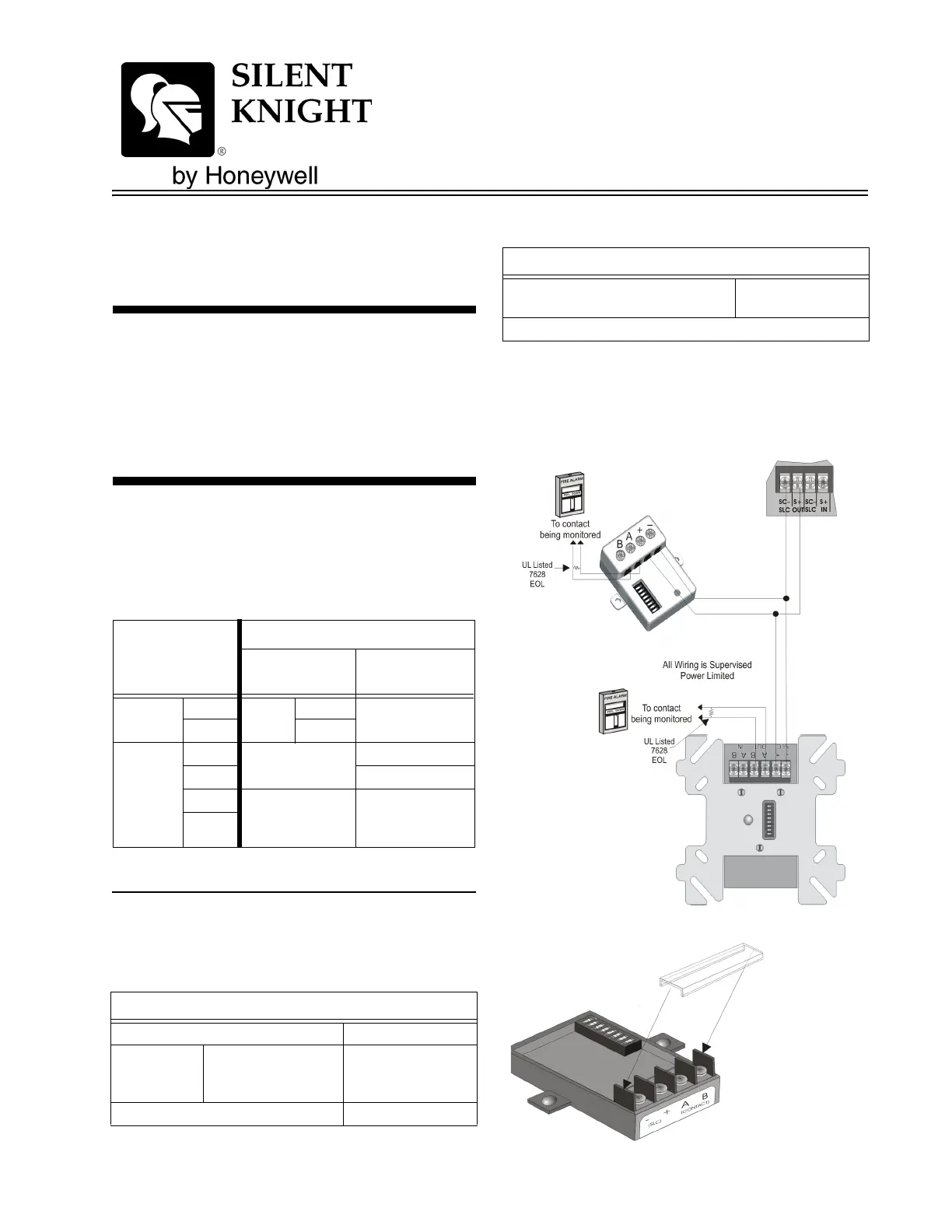
Wiring the SD500-AIM / MIM
Note: Installation and wiring of these devices must be done in
accordance with NFPA 72 and local ordinances.
Terminate the wiring as shown in Table 1. See
also Figure 1 or Figure 2
Specifications
Table 2 lists the operating specifications for the
SD500-AIM and the SD500-MIM.
Impedance for Earth Ground Fault is 0 Ω for all
terminals.
Figure 1: Class B Wiring the SD500-AIM & SD500-MIM
Table 1: Wire Connections
SD500-AIM
SD500-MIM
Terminals
To:
FACP or SLC
Loop Terminals
Contact
SLC
–
SLC
OUT
SC–
+S+
Contact
A out
CLASS A
OR B
To N.O. Contact
B out To N.O. Contact
A IN
CLASS A ONLY
(SD500-AIM Only)
End of Loop A
End of Loop B
B IN
Table 2: SD500-AIM and SD500-MIM Specifications
Specifications
Max. Line resistance 50Ω
Max. Alarm
Current
One device in alarm
23mA. 46 mA for two
devices in alarm.
.5 mA for each addi-
tional device in
alarm.
Max. Voltage 33 V
Operating Temperature 0° to 49° C
(32° to 120° F)
Indoor use only
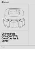
Table 2: SD500-AIM and SD500-MIM Specifications
Specifications
Alternate
Construction
Produktspecifikationer
| Varumärke: | Silent Knight |
| Kategori: | Detektor |
| Modell: | SD500-MIM |
Behöver du hjälp?
Om du behöver hjälp med Silent Knight SD500-MIM ställ en fråga nedan och andra användare kommer att svara dig
Detektor Silent Knight Manualer

19 September 2024

19 September 2024

19 September 2024

19 September 2024

19 September 2024

18 September 2024
Detektor Manualer
- Benewake
- Popp
- Velleman
- Milwaukee
- AcuRite
- Safescan
- Smartwares
- Konig
- Black Decker
- Edimax
- RIDGID
- Vemer
- Bearware
- Metrix
- Bosch
Nyaste Detektor Manualer

12 Oktober 2025

26 September 2025

26 September 2025

26 September 2025

25 September 2025

21 September 2025

20 September 2025

18 September 2025
13 September 2025
13 September 2025