Simrad RECON UI Cover Bruksanvisning
Simrad ej kategoriserat RECON UI Cover
Läs gratis den bruksanvisning för Simrad RECON UI Cover (2 sidor) i kategorin ej kategoriserat. Guiden har ansetts hjälpsam av 48 personer och har ett genomsnittsbetyg på 4.0 stjärnor baserat på 3 recensioner. Har du en fråga om Simrad RECON UI Cover eller vill du ställa frågor till andra användare av produkten? Ställ en fråga
Sida 1/2
Recon
™
Mount UI Cover
Installation Guide: EN
Document version: 001
⚠WARNING: This product must be installed in
accordance with the instructions provided. Failure to do
so could result in personal injury, damage to your vessel
and/or poor product performance.
⚠WARNING: Performing service or maintenance
without rst disconnecting the battery can cause product
damage, personal injury, or death due to re, explosion,
electrical shock, or unexpected motor starting. Always
disconnect the battery cables from the battery before
maintaining, servicing, installing, or removing motor
components.
In the box
•1x Recon™ mount UI cover
•2x #6 x 3/8, pan, T15 Torx
®
, SS screws
•2x M3-0.5 x 8, flange, hex, SS screw
Tools needed
•#2 Phillips screwdriver
•5/32 in Allen key
•2 mm Allen key
•T15 Torx
®
screwdriver
•Torque wrench
Introduction
The mount user interface cover (UI cover) contains the
circuit boards for the keys and LEDs on the mount. The
UI cover also protects the main circuit board and the
connections inside the trolling motor mount.
Removal
To remove the existing mount UI cover:
1 Disconnect the trolling motor power cable from the
battery (or unplug the power cable if using a plug and
receptacle).
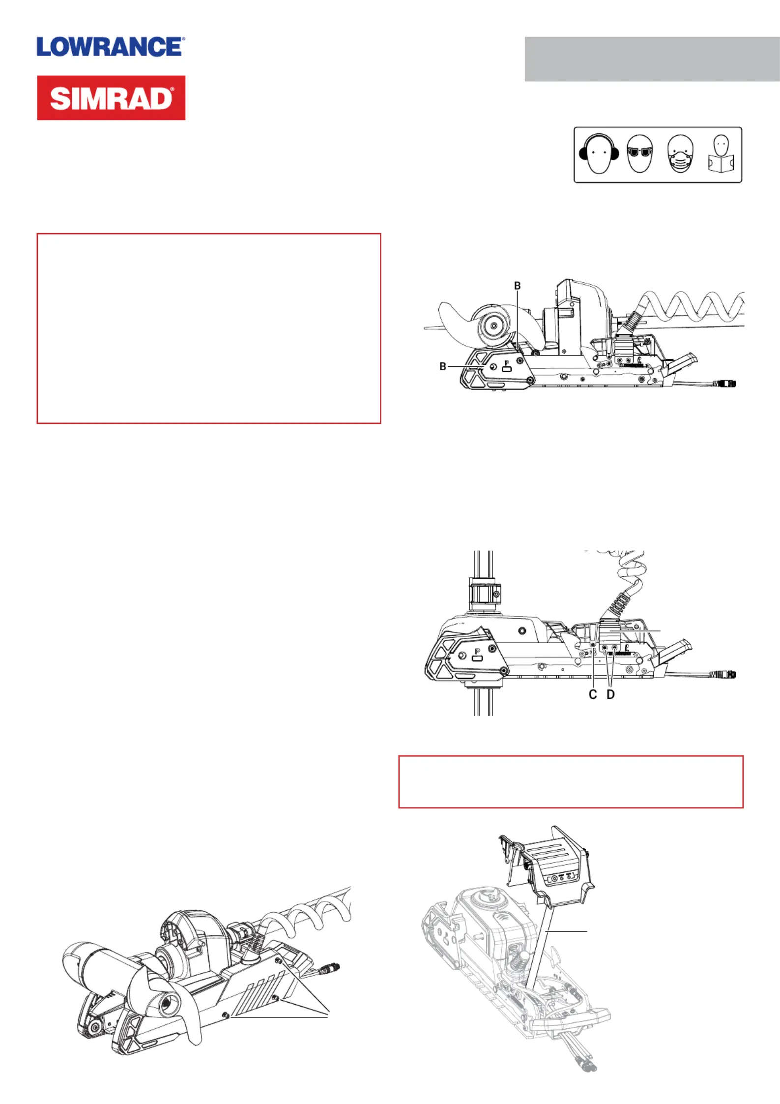
2 While your trolling motor is stowed or deployed, use a
#2 Phillips screwdriver to loosen the side plate screws
on both sides of the mount ().A
¼Note: The screws are retained by washers.
A
3 Remove the side plates, taking care not to damage the
locating tabs as they leave their slots ().B
4 Deploy the trolling motor.
5 Use a 2 mm Allen key to remove the screw from both
sides of the UI cover ().C
6 Use a 5/32 in Allen key to loosen the two screws () that D
secure the coil cable bracket 2–3 full rotations. These
screws have a blue thread-locking compound applied to
them. Ease the coil cable bracket () outward from the E
mount.
E
7 Lift the UI cover upward to separate it from the mount.
⚠WARNING: Do not lift the UI cover more than 30 cm
(~12 in) above the mount, to avoid damaging the ribbon
cable () that remains connected to the mount.F
F
Produktspecifikationer
| Varumärke: | Simrad |
| Kategori: | ej kategoriserat |
| Modell: | RECON UI Cover |
Behöver du hjälp?
Om du behöver hjälp med Simrad RECON UI Cover ställ en fråga nedan och andra användare kommer att svara dig
ej kategoriserat Simrad Manualer

12 September 2025
11 September 2025
11 September 2025
11 September 2025
11 September 2025
11 September 2025
11 September 2025
11 September 2025
11 September 2025
10 September 2025
ej kategoriserat Manualer
Nyaste ej kategoriserat Manualer
3 April 2026
3 April 2026
3 April 2026
3 April 2026
3 April 2026
3 April 2026
3 April 2026
3 April 2026
3 April 2026