TKM MX300 Bruksanvisning
TKM
ej kategoriserat
MX300
Läs gratis den bruksanvisning för TKM MX300 (12 sidor) i kategorin ej kategoriserat. Guiden har ansetts hjälpsam av 3 personer och har ett genomsnittsbetyg på 4.5 stjärnor baserat på 2 recensioner. Har du en fråga om TKM MX300 eller vill du ställa frågor till andra användare av produkten? Ställ en fråga
Sida 1/12

!
1
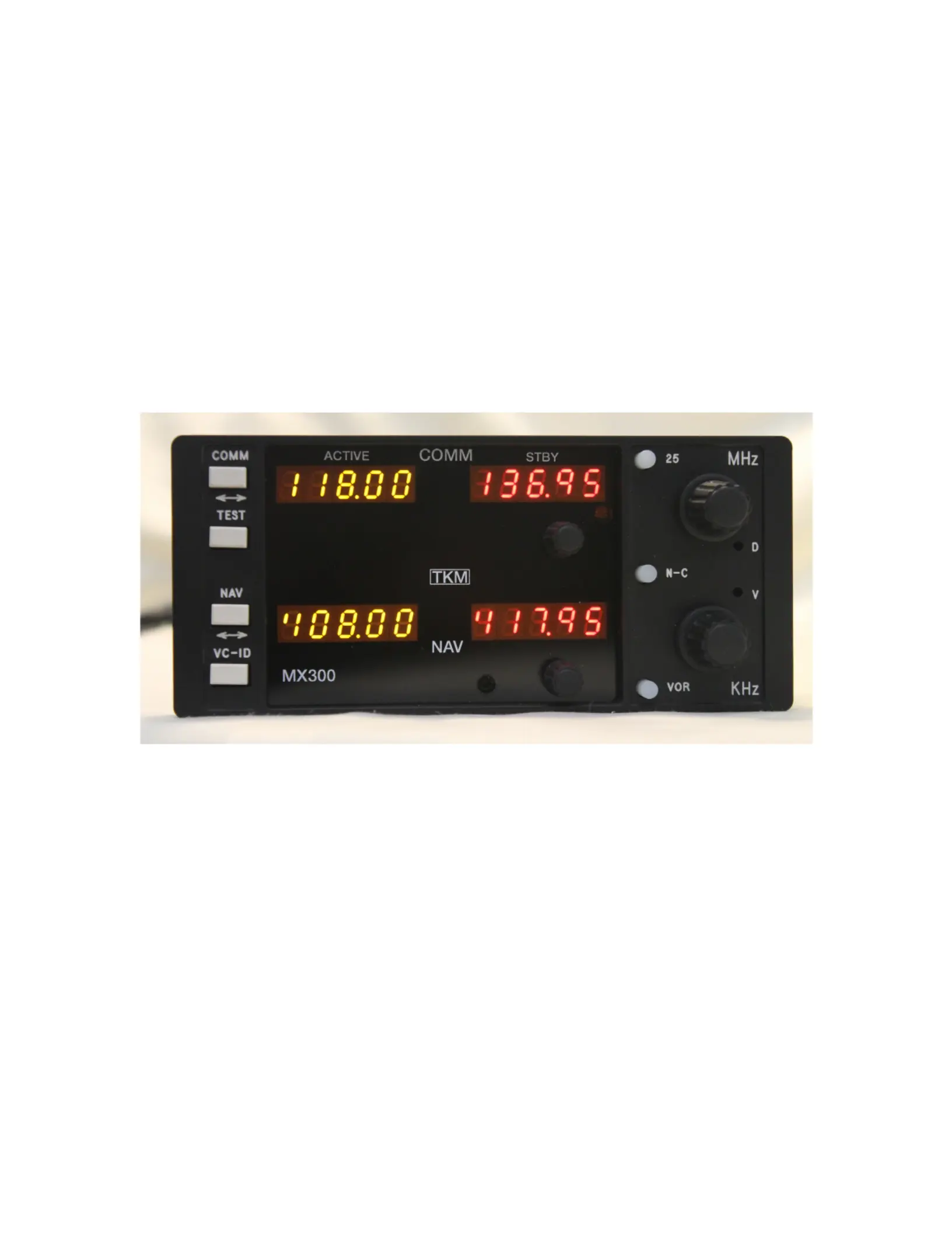
MX300 NAV - COMM OWNER'S MANUAL
TKM, INC
14811 NORTH 73
rd
STREET
SCOTTSDALE, AZ 85260
PART
#
MN0300, REV. 4
NOV 10, 2008

!
2
I. INTRODUCTION
This manual contains information on the Michel MX300, manufactured by TKM, Inc. The
information includes installation, operation, mechanical and electrical descriptions, alignment
and test considerations. The MX300 is authorized by the Federal Aviation Administration to
TSO C34e, C36e, C37c, C38c, C40b and has met the test requirements ofRTCAlDO-160B.
A. Purpose of Equipment
The equipment is a 760 channel communication (COMM) transceiver for use in aviation services
and a 200 channel navigation (NAV) receiver to provide VOR
I
LOC signals
to navigational converters. The NA V receiver also provides frequency selection for remote
mounted Distance Measuring Equipment and Glide slope Receivers. Navigation converter
circuitry is included to interface ARC CDIs normally used with RT328T.
The MX300 is designed to be a direct replacement for the Cessna/ARC328T. The unit is
dimensionally identical to the ARC units and can therefore use existing aircraft installations.
Except for improved performance characteristics, the unit is electrically interchangeable with
the ARC unit and will provide the proper audio, navigation, and channeling signals for
existing installations. New installations can be made using RT328T installation kits.
Additionally, the MX300 will directly replace the following NAV/COMMs:
RT308C RT328A RT508A RT528A
RT328C RT528E
RT328D
The RT308C, RT328A, and RT528A use pin L instead of pin BB of J4 to output the NAV
demod signal. The MX300 may be modified in the field as described in Section VI.
While not manufactured by TKM, an adapter tray may be found commercially which permits
replacement of the following: RT514R, RT515R, RT515A-l, RT517, RT540.
B. Equipment Description
The unit features digital (LED) displays for active (yellow) frequency channel and
standby (red) frequency channel for both COMM and NAV.
For channel selection a MHz knob and a KHz knob are provided. For 25 KHz increments in
COMM, a 25 KHz button is provided. To activate COMM or NA V frequency selection, an
N/C button is provided. A tic appears in the selected standby channel display.
Channel selection operates on the standby channel only. When the desired channel is indicated
in the standby display, it may be placed into the active position by depressing the "Flip-flop"
button located between the displays. The active channel is then placed into the standby position.
!
The NAV receiver features a VC-ID button to permit selection of voice or ident reception.
In
the ident condition a tic is displayed on the active NAV channel display.
The COMM transceiver features a test button that overrides the squelch to verify proper
receiver operation and to allow reception of weak signals. Also provided on the active
COMM display is a tic to indicate transmitter power output.

!
3
The master power switch is integrated with the volume control.
The VOR test button, located on the front panel, allows injection of a 0 degree FROM
bearing into the navigation converter circuits. A bearing adjustment can then be made
through the adjustment hole (V) by the KHz switch.
The MX300 is comprised of eight replaceable subassemblies. Five of the subassemblies are
contained in shielded modules in order to reduce radio frequency interference. The five are
the NAV receiver, the NAV synthesizer, the COMM receiver, the COMM synthesizer, and
the Transmitter.
The remaining three subassemblies are the Rear Panel Assembly, the Front Panel Assembly
and the Computer Board. Integrated into the Rear Panel Assembly are the audio amplifier,
power converter, power line filter, remote channeling circuits, and the
T/
R switching. The
Front Panel assembly contains the digital displays and corresponding driver circuits, function
select switches, and volume controls. The Computer Board contains the microprocessor as
well as memory and program storage.
Also contained on the computer board are the audio processing and NAV converter
circuits.
The subassemblies are interconnected with plugs to facilitate module replacement. For
equipment repair it is typically recommended that complete subassemblies be replaced.
As an aid to locating a problematic subassembly, a set of analog test points is provided. The
analog test points include the receiver tuning voltages, the synthesizer control voltages and
the AGC lines.
!
!
!
!
!
!
!
!
!
!
!
!
!
!
!
!
!
!
Produktspecifikationer
Varumärke: | TKM |
Kategori: | ej kategoriserat |
Modell: | MX300 |
Behöver du hjälp?
Om du behöver hjälp med TKM MX300 ställ en fråga nedan och andra användare kommer att svara dig
ej kategoriserat TKM Manualer
20 Juli 2025
ej kategoriserat Manualer
- Peplink
- Cherry
- Yadea
- DataVideo
- Leisure
- Maestro
- Matrix Audio
- Fuxtec
- Entes
- Microchip
- Bosch
- Beaba
- Philips
- PolarPro
- Intermatic
Nyaste ej kategoriserat Manualer
20 Juli 2025
20 Juli 2025
20 Juli 2025
20 Juli 2025
20 Juli 2025
20 Juli 2025
20 Juli 2025
20 Juli 2025
20 Juli 2025
20 Juli 2025