Valcom V-5331215 Bruksanvisning
Läs gratis den bruksanvisning för Valcom V-5331215 (2 sidor) i kategorin högtalare. Guiden har ansetts hjälpsam av 26 personer och har ett genomsnittsbetyg på 4.5 stjärnor baserat på 7 recensioner. Har du en fråga om Valcom V-5331215 eller vill du ställa frågor till andra användare av produkten? Ställ en fråga
Sida 1/2
Issue 2
947190
1
by
PagePac
®
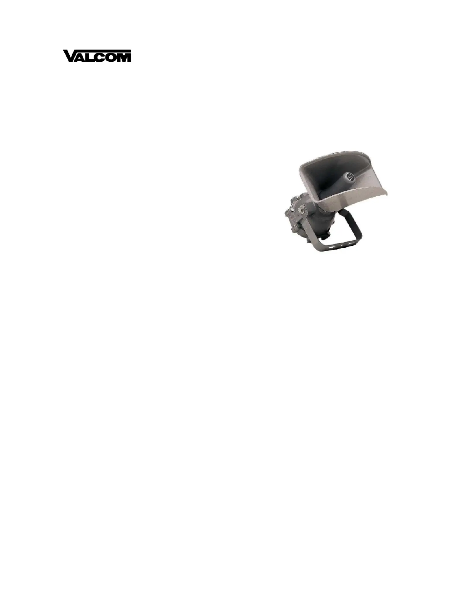
40 WATT EXPLOSION PROOF HORN
V-5331215A
INTRODUCTION
Explosion Proof Horn Speakers are constructed so
that all electrical components are sealed from the
atmosphere and may be used in areas where
ammable substances are present. The explosion
proof speakers require some assembly before
installation (See Figure 1).
Explosion proof speakers are mounted, using the
U-shaped mounting bracket (Attached to each
speaker). These brackets are intended primarily for
mounting on at surfaces, and each bracket has three
holes which may be used for installing mounting
hardware. Speaker position in the vertical axis may be
adjusted by loosening the bolts that secure the
bracket to the speaker body (See Figure 1).
SPECIFICATIONS
Features
• UL/CSA Listed
•Heavy Duty Construction
•Omni-Directional Mounting Bracket
•5 Tap Settings (2.5W, 5W, 10W, 20W, 40W)
Nominal Specications
•Dispersion: Wide Angle
• Input: 70.7V Line
• Output: 101dB - 113dB
Dimensions/Weight
•16.50” Diameter x 21.50” D
(41.91cm x 54.61cm)
• 27 lbs. (12.2 kg)
Environment
•Temperature: -4 to +131°F (-20 to +55°C)
• Humidity: 0 to 95%
INSTALLATION
Mounting
Separate the horn and the base of the speaker by
holding the base of the speaker tightly and turning the
horn counterclockwise (See Figure 1, View 1).
Separate the two halves of the speaker base by
removing the eight bolts (See Figure 1, View 2).
Make the conduit entry into the speaker as required
by local ordinances for the class and type of speaker
used (See Figure 1, View 3).
On the speaker cable, separate the inner wires for a
distance of 3 or 4 inches by stripping away insulation
from the main cable. If using shielded cable, the inner
wire without insulation is the shield wire. Strip
approximately 1/2 inch of insulation from the end of
each of the smaller insulated wires.
Note: The cable must enter the speaker through a
conduit that has been installed according to local
ordinances for the class and type of speaker used.
Connect the wires on terminals 1 and 2. If shielded
cable is used, either splice the shield wire to provide a
continuous shield to the next speaker or clip the
shield wire at the point where it emerges from the
main cable, as appropriate. The shield wire should not
be terminated on the speaker.
POWER ADJUSTMENTS
If necessary, remove the power tap selection wire
(White wire) and reattach it to the desired power tap.
The numbers on the terminal strip indicate the output
in Watts for a 70Volt paging system (On a 25Volt
paging system, the output will be approximately 1/8 of
that indicated (See Table 1). Reassemble the two
halves of the speaker case by reinstalling the eight
bolts.
Produktspecifikationer
| Varumärke: | Valcom |
| Kategori: | högtalare |
| Modell: | V-5331215 |
| Bredd: | 335.6 mm |
| Djup: | 444.5 mm |
| Höjd: | 152.4 mm |
| Diameter: | 12150 mm |
| Rekommenderad användning: | Andra |
| Ljudutgångskanaler: | 1.0 kanaler |
| Högtalarplacering: | Ceiling-mountable, Wall-mountable |
| Antal förare: | 1 |
| Uteffekt (RMS): | 40 W |
| Frekvensområde: | - hz |
| Anslutningsteknologi: | Kabel |
Behöver du hjälp?
Om du behöver hjälp med Valcom V-5331215 ställ en fråga nedan och andra användare kommer att svara dig
högtalare Valcom Manualer

1 April 2026
21 September 2025
14 Augusti 2025
5 Augusti 2025
4 Augusti 2025
4 Augusti 2025
4 Augusti 2025
4 Augusti 2025
4 Augusti 2025
4 Augusti 2025
högtalare Manualer
Nyaste högtalare Manualer
3 April 2026
3 April 2026
2 April 2026
2 April 2026
1 April 2026
30 Mars 2026
30 Mars 2026
29 Mars 2026
29 Mars 2026
29 Mars 2026