Valcom VIP-172L Bruksanvisning
Valcom
internt kommunikations system
VIP-172L
Läs gratis den bruksanvisning för Valcom VIP-172L (3 sidor) i kategorin internt kommunikations system. Guiden har ansetts hjälpsam av 2 personer och har ett genomsnittsbetyg på 4.0 stjärnor baserat på 1.5 recensioner. Har du en fråga om Valcom VIP-172L eller vill du ställa frågor till andra användare av produkten? Ställ en fråga
Sida 1/3

1 947632
CAUTION: To reduce the risk of electric shock,
Do not remove cover.
No user serviceable parts inside.
Refer servicing to qualied service personnel.
CAUTION
RISK OF ELECTRIC SHOCK
DO NOT OPEN
This symbol indicates that dangerous
voltage constituting a risk of electric
shock is present within this unit.
This symbol indicates that there are
important operating and maintenance
instructions in the literature accompanying
this unit.
ISSUE 5
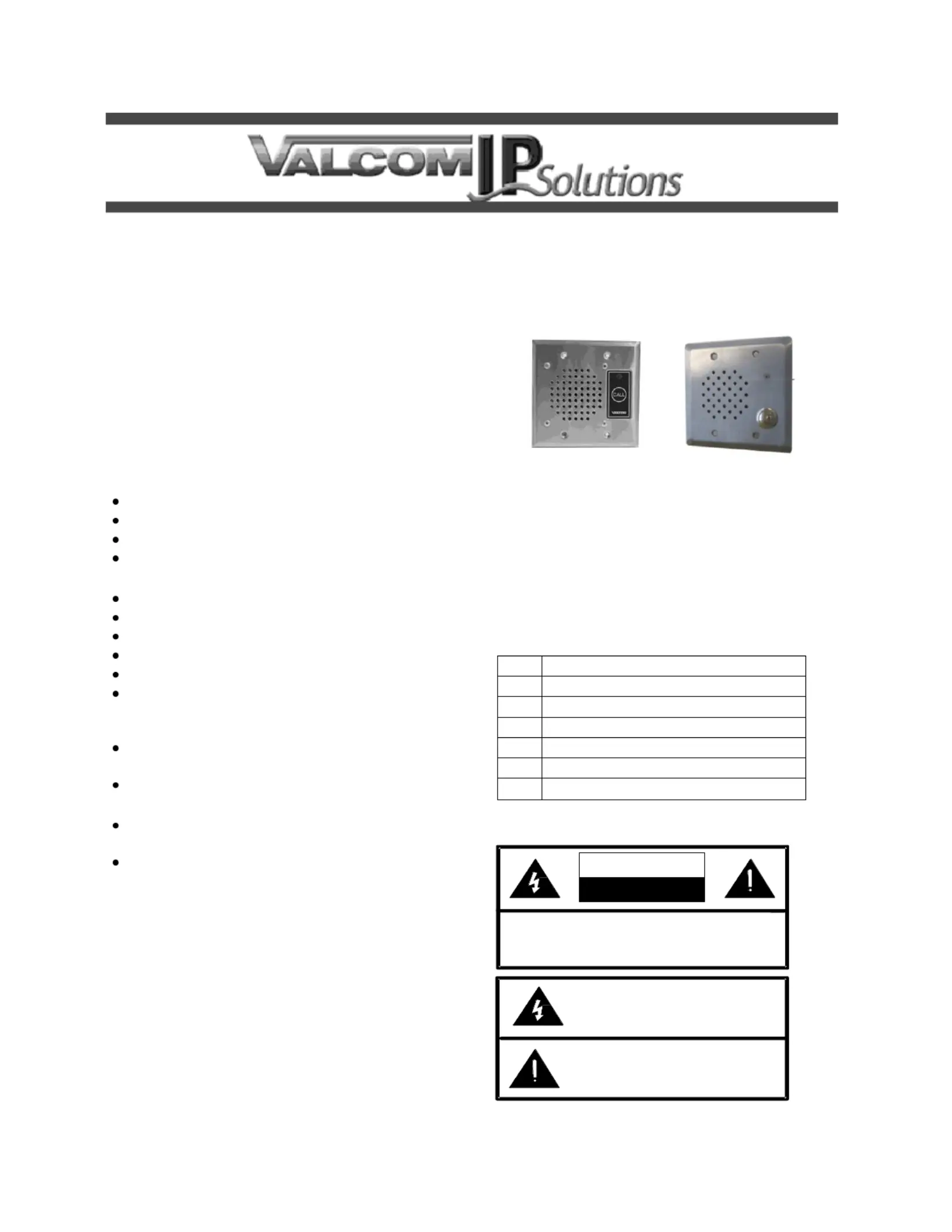
VIP-172L IP DoorPhone/Intercom
INTRODUCTION
The VIP-172L IP Talkback Doorphone/Intercom
allows communication to Valcom FXS units
(VIP-811 -812, -814) and SIP Based telephone ,
systems via a managed IP-based LAN/WAN.
SPECIFICATIONS
Access Methods
PBX, FXO Port w/VIP-811
POTS telephone set w/VIP- 811
Valcom M Cast Page Group
SIP enabled telephone system –
Features
-45 for network connection RJ
1 Form C contact
LED Status Indicator
Network activity LEDs
802.3af compliant
Door Opening Contact Provided
Dimensions/Weight V- -172L VR
H x 4.5" W x 1.75" D 4.5”
(11.43cm H x 11.43cm W x cm D) 4.45
Weight: 1.68 lbs. (0.76 kg)
Dimensions/Weight V- -BR/ST 172L
4.5” H x 4.5" W x 1.3" D
(11.43cm H x 11.43cm W x 3.3cm D)
Weight: .55 lbs. (0.25 kg)
Nominal Specications
Input Impedance: 600 Ohms
Input Level: -10dBm
Output Impedance: 600 Ohms
Output Level: -10dBm nominal
Relay Current: 1 AMP @ 24VDC
Nominal Power Requirements
Via 802.3af PoE Ethernet Switch: Class 3
(12.95W)
VIP- -BRASS/SS 172L VIP-172L- VRSS
Environment
VIP-172L Network Interface
Temperature: 0 to +40° C
Humidity: 0 to 85% non-precipitating
VIP-172L Doorplate:
Suitable for indoor or outdoor installation
Packing List
Qty
Item
1
VIP-172L Network Interface
1
VIP-172L Door plate
1
VSP Document
4
Tamper Hardware (VR unit only) SS
4
SS Screws (Brass/SS)
1
Setup CD
Precautionary Designations

2 947632
FCC Information
This equipment has been tested and found to
comply with the limits for a Class A digital
device, pursuant to Part 15 of the FCC Rules.
These limits are designed to provide
reasonable protection against harmful
interference when the equipment is operated
in a commercial environment. This
equipment generates, uses and can radiate
radio frequency energy and if not installed
and used in accordance with the instruction
manual, may cause harmful interference to
radio communications. Operation of this
equipment in a residential area may cause
harmful interference in which case the user
will be required to correct the interference at
his own expense.
INSTALLATION
Operation:
The VIP-172L provides door intercom access via
network connection to customer telephone
system or stand alone telephone set. Interface to
customer telephone system can be via SIP
registration or FXO port (with VIP-811). Pressing
the call button on the door plate initiates a call to
one of the above telephone system interfaces,
and the call assurance LED on the door plate
begins to ash. When the call is answered, a
hands-free communications path is established to
the door plate, and the call assurance LED on the
door plate changes to solid. At any time during
the call if the # key is pressed, the form C relay
on the door plate operates for 3 seconds for
activation of customer supplied door entry
equipment.
Mounting
For enhanced protection against static
electrical discharge, it is recommended the
faceplate shipped with the VIP-172L be
installed into a grounded electrical box.
The VIP-172L Doorplate is designed for double
gang FD electrical box mounting and must be
within 300 meters of the VIP-172L Network
Interface. See NEMA OS 3-2002 sec.1.2.3.5 for
FD box specications.
The VIP-172L Network Interface is designed for
wall or table mounting and must be within 100
meters of the network switch.
Table: Provided with the VIP-172L are four
rubber stick on feet. Peel these feet o their
carrier backing and place at the four corners of
the bottom of the unit.
Wall: Using the template and wood screws
provided, secure the VIP-172L Network interface
to the wall.
Power Connections
The only method of powering a VIP-172L
Network Interface is via a power over Ethernet
switch or power injector meeting the 802.3af
specication .
Make all required signal connections before
connecting to Ethernet switch or power injector
meeting the 802.3af specication.
Network Connection
The VIP-172L Network Interface has one CAT-5
RJ-4 NETWORK connector and one CAT-5 5
RJ- DOOR PLATE connector on the front 45
panel.
Use the supplied CAT-5 patch cable to connect
the NETWORK connector of the VIP-172L
Network Interface to an Ethernet switch.
Signal Connections
Connect CAT-5 RJ-45 using EIA/TIA 568B
Standard to the DOOR PLATE connector of the
VIP-172L Network Interface then to the RJ-45
connector of the VIP-172L Door Plate.
Door Relay Connections
Access to the form C relay is provided via a three
pin screw terminal block on the VIP-172L Door
plate. The common contact is the middle
terminal with the normally open contact closest to
the RJ-45 Connector. Normally closed contact is
furthest from the RJ-45 connector. Relay contacts
are rated for 1A @ 24VDC.
Aux I nput
Aux input on the VIP-172L Network Interface
accepts line level audio such as background
music and broadcasts it through the door plate
speaker. When the call button is pressed, the aux
input is muted and remains muted until the call is
terminated.
Status Indicator Lights
The V -172L Door plate is equipped with a IP
status indicator LED. LED ashes when the call
button is pressed and steady when the call is
connected.
The VIP-172L Network Interface has 3 status
indication lights on the side panel:

3 947632
CAT 5
300 METERS MAX.
N.O.
COM
N.C.
TO LAN / WAN
Network
AUX
Door Plate
Network
Interface
Door Plate
STATUS: Flashes during normal operation, and
solid when unit in reset.
LINK: Indicates 100 Mbit Ethernet connection
when illuminated. No activity indicates 10 Mbit
connection.
ACT: Indicator ashes to indicate network
activity.
TECHNICAL ASSISTANCE
Assistance in troubleshooting is available from
the factory. Call (540) 563-2000 and press 1 for
Technical Support or via email at
support@valcom.com.
When requesting assistance, you should include
all available information. It is strongly suggested
that you go to the web site and follow the trouble
resolution procedure at http://voip.valcom.com.
Valcom equipment is not eld repairable.
Valcom, Inc. maintains service facilities in
Roanoke, VA. Should repairs be necessary,
attach a tag to the unit clearly stating your
company name, address, phone number, contact
person and the nature of the problem.
Send the unit to:
Valcom, Inc.
Repair & Return Dept.
5614 Hollins Road
Roanoke, Va. 24019-5056
Figure 1. Interconnections
VALCOM LIMITED WARRANTY
Valcom, Inc. warrants its products only to the original purchaser, for its own use, to be free from defects in materials and workmanship under
conditions of normal use and service for a period of one year from the date of shipment. This Limited Warranty obligation shall be limited to the
replacement, repair or refund of any such defective device within the warranty period, provided that:
1. inspection by Valcom, Inc. indicates the validity of the claim;
2. the defect is not the result of damage, misuse or negligence after the original shipment;
3. the product has not been altered in any way or repaired by others and that factory sealed units are unopened (a service charge plus parts
and labor will be applied to units defaced or physically damaged);
4. freight charges for the return of products to Valcom are prepaid;
5. all units 'out of warranty' are subject to a service charge. The service charge will cover minor repairs (major repairs will be subject to
additional charges for parts and labor).
This Limited Warranty is in lieu of and excludes all other warranties, expressed or implied and in no event shall Valcom, Inc. be liable
for any anticipated prots, consequential damages, loss of time or other losses incurred by the buyer in connection with the purchase,
operation, maintenance, installation, removal or use of the product. The maximum liability of Valcom under this warranty is limited to
the purchase price of the specic Product covered by the warranty.
Disclaimer. Except for the Limited Warranty provided herein, the product is provided “as is” without any warranty of any kind whatsoever -
including, without limitation, any WARRANTY OF MERCHANTABILITY, FITNESS FOR A PARTICULAR PURPOSE OR NON-INFRINGEMENT.
This warranty specically excludes damage incurred in shipment. In the event a product is received in damaged condition, the carrier should be
notied immediately. Claims for such damage should be led with the carrier involved in accordance with the F.O.B. point.
Headquarters:
Valcom, Inc.
5614 Hollins Road Roanoke, VA 24019- 5056
Phone: (540) 563-2000 FAX: (540) 362-9800
Produktspecifikationer
Varumärke: | Valcom |
Kategori: | internt kommunikations system |
Modell: | VIP-172L |
Certifiering: | IETF SIP (RFC3261)\r\nIETF IGMP version 3 (RFC3376)\r\nIETF RTP (RFC1889)\r\nIETF RFC2833 |
Videosamtal: | Nej |
Antal knappar: | 1 |
Kompatibla produkter: | PoE: 802.3af, class 3 |
Produktens färg: | Rostfritt stål |
Produktstorlek (BxDxH): | 114.3 x 33 x 114.3 mm |
Tangentbordsbelysning: | Nej |
Material, hölje: | Rostfritt stål |
Högtalartelefon: | Ja |
Kamera inkluderad: | Nej |
IP-anslutningsbar: | Ja |
DECT-ansluten: | Nej |
Moduler kvantitet (max): | 1 modul/-er |
Överföring till externa nummer: | Nej |
Behöver du hjälp?
Om du behöver hjälp med Valcom VIP-172L ställ en fråga nedan och andra användare kommer att svara dig
internt kommunikations system Valcom Manualer
19 Juli 2025
19 Juli 2025
19 Juli 2025
19 Juli 2025
19 Juli 2025
19 Juli 2025
14 Juli 2025
14 Juli 2025
internt kommunikations system Manualer
Nyaste internt kommunikations system Manualer
11 Juli 2025
10 Juli 2025
4 Juli 2025
30 Juni 2025
29 Juni 2025
29 Juni 2025
22 Juni 2025
18 Juni 2025
16 Juni 2025
14 Juni 2025